Local coil and construction method, magnetic resonance apparatus and method for measuring magnetic resonance signals

A magnetic resonance signal and local coil technology, which is applied in magnetic resonance measurement, measurement of magnetic variables, measurement devices, etc., can solve problems such as reducing the flexibility of local coils

Inactive Publication Date: 2011-12-21
SIEMENS AG
View PDF0 Cites 12 Cited by
  • Summary
  • Abstract
  • Description
  • Claims
  • Application Information

AI Technical Summary

Problems solved by technology

[0006] However, the problem when using such antenna groups is that high-frequency currents in one antenna turn can induce voltages in an ad

Method used


Image

  • Local coil and construction method, magnetic resonance apparatus and method for measuring magnetic resonance signals
  • Local coil and construction method, magnetic resonance apparatus and method for measuring magnetic resonance signals
  • Local coil and construction method, magnetic resonance apparatus and method for measuring magnetic resonance signals

Examples


Embodiment Construction

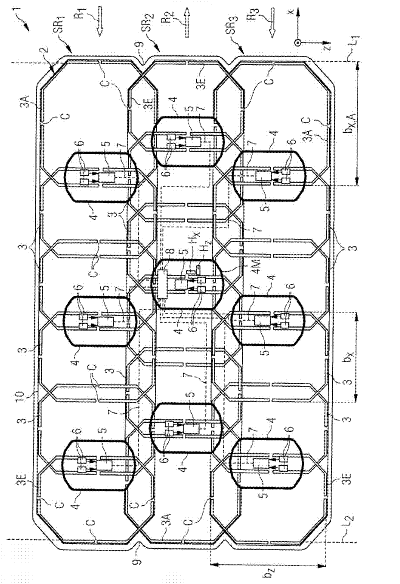
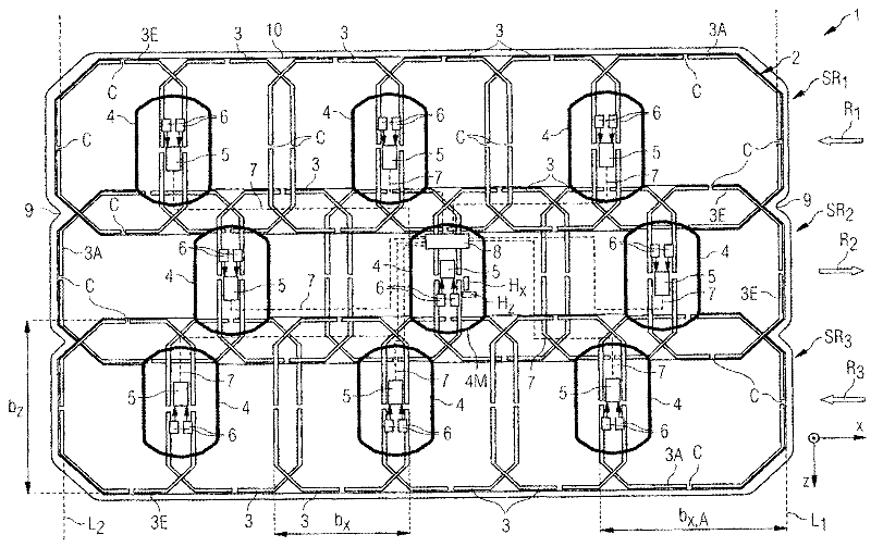
[0041] figure 1 The local coil 1 shown has a total of three rows of SR 1 、SR 2 、SR 3 , which each have six individual antenna turns 3, 3A. These row SR 1 、SR 2 、SR 3 extends longitudinally along the local coil 1, at figure 1 where it lies in the coordinate system x / z plane of the magnetic resonance tomograph and is oriented longitudinally in the x direction. In principle, however, the local coils can be positioned arbitrarily. Nevertheless, for simplicity, the following is based on figure 1 The spatial directions x, y in , but the present invention is not limited thereto.

[0042] The individual antenna turns 3, 3A each have a conductor track, which describe an octagon, each comprising four longer sides and four shorter sides diagonally connecting the longer sides (hereinafter also referred to as "corner segments") . The longer side runs parallel to the outer edge of the local coil 1, ie at figure 1 It extends along the x-direction and the z-direction. On these lo...


PUM


Abstract

The invention relates to a local coil (1) with a magnetic resonance antenna group (2) comprising a plurality of antenna turns (3, 3A, 3E) arranged in adjacent rows (SR1, SR2, SR3) ), the antenna turns arranged adjacent to each other are inductively decoupled from each other through geometric overlap (UX, UZ), and the antenna turns are staggered in alternate directions (R1, R2, R3), so that two in a row The overlapping area of ​​the antenna turns is staggered from the overlapping area of ​​two antenna turns in an adjacent row, at least some of the antenna turns are designed to compensate for the stagger, so that they are redrawn as different areas and thus the antenna lines Adjacent rows of turns in the stagger direction terminate substantially at the front end and at the rear end, respectively, on a straight line ( L1 , L2 ) transverse to the stagger direction. The invention also relates to a magnetic resonance apparatus with such a local coil, a method for constructing such a local coil and a method for measuring magnetic resonance signals.

Description

technical field [0001] The invention relates to a local coil for a magnetic resonance apparatus with a magnetic resonance antenna group comprising a plurality of antenna turns arranged in parallel adjacent rows. Furthermore, the invention relates to a magnetic resonance apparatus with such a local coil, a method for constructing the local coil, and a method for measuring magnetic resonance signals. Background technique [0002] During magnetic resonance examinations of certain organs or body parts of a patient, so-called surface antennas are used to receive magnetic resonance signals (MR signals) and, if applicable, to transmit the high-frequency signals necessary to excite nuclear spins. These surface antennas are placed relatively close to the organ or body part to be examined during the examination, preferably directly on the surface of the patient's body. Because they are placed near the area of ​​interest, these surface antennas have the advantage that they have a larg...

Claims


Application Information

Patent Timeline
IPC IPC(8): G01R33/36G01R33/3415
CPCG01R33/365G01R33/3415G01R33/3657G01R33/36
Inventor 斯蒂芬.比伯伊冯.坎迪达斯卡斯滕.扬斯
Owner SIEMENS AG
Why Eureka
Try Eureka