
Method of Controlling Bottom of Roadway by Deep Hole Interval Blasting

A technology for roadway and deep hole, which is applied in the field of deep hole interval blasting control of roadway bottom, can solve the problems of deterioration, insufficient depth, and poor control effect of roadway bottom, and achieves the effect of maintaining stability and reducing the amount of bottom.

Active Publication Date: 2011-12-21
TIANDI SCI & TECH CO LTD
View PDF2 Cites 3 Cited by
  • Summary
  • Abstract
  • Description
  • Claims
  • Application Information

AI Technical Summary

Problems solved by technology

In fact, the main cause of the impact of the roadway floor and floor is the stress concentration of the surrounding rock. The active transfer and release of stress is to fundamentally solve the problem of roadway floor and floor impact. A few scholars have realized this problem and adopted blasting The pressure relief method is used to prevent and control bottom sag. However, because the understanding of the bottom sag mechanism is not deep enough, in practical applications, only floor blasting is often carried out, and the leading influence of roadway side support pressure on the bottom sag is ignored, resulting in the control of roadway bottom sag. not effectively
In addition, the setting of the charging parameters is not reasonable enough, and the setting of the charging interval is blind, which leads to the improvement of the mechanical characteristics of the roadway floor and the stress environment are not obvious, or even deteriorated, and finally the problem of bottom slugs cannot be effectively treated, which seriously restricts the coal mine. Safe and efficient production

Method used


Image

  • Method of Controlling Bottom of Roadway by Deep Hole Interval Blasting
  • Method of Controlling Bottom of Roadway by Deep Hole Interval Blasting
  • Method of Controlling Bottom of Roadway by Deep Hole Interval Blasting

Examples


Embodiment Construction

[0022] The specific implementation manners of the present invention will be further described in detail below in conjunction with the accompanying drawings and embodiments. The following examples are used to illustrate the present invention, but are not intended to limit the scope of the present invention.

[0023] In this embodiment, a working face with a coal seam thickness of 3 m is taken as an example to introduce the treatment method for roadway undercut.

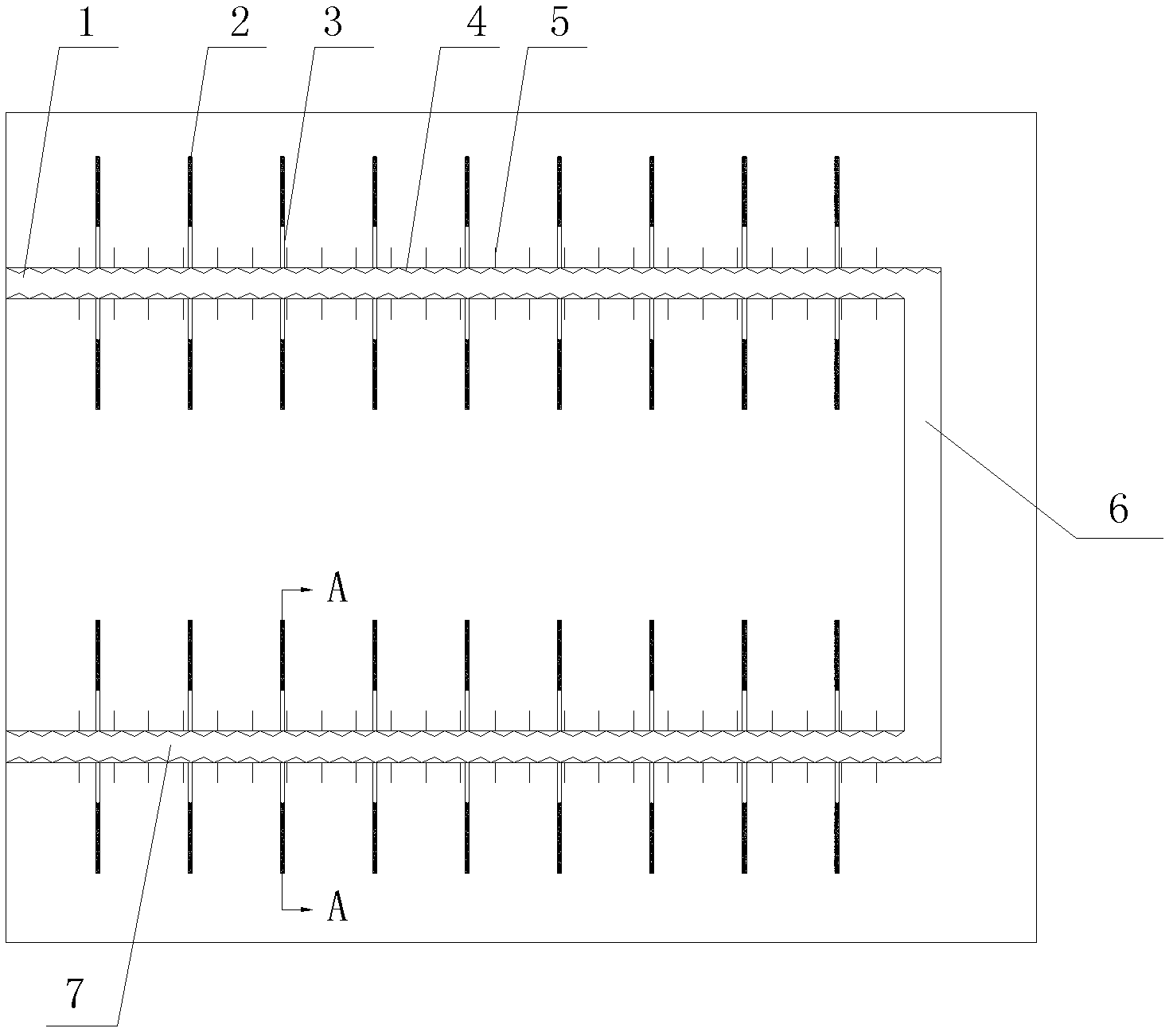
[0024] Such as figure 1 As shown, firstly, in the underground mining area, roadways such as inlet air entry 1, incision 6 and return air entry 7 are excavated in the underground mining area; Lay diamond-shaped metal mesh 4 on the top plate and the two sides of the return air alley 7, and the lap length between the nets is 100mm; the roof and the two sides after the netting are installed with an anchor rod 5 with a length of 2.5m, and the anchor rod The row spacing between 5 is 600mm×800mm.

[0025] After completing ...


PUM


Abstract

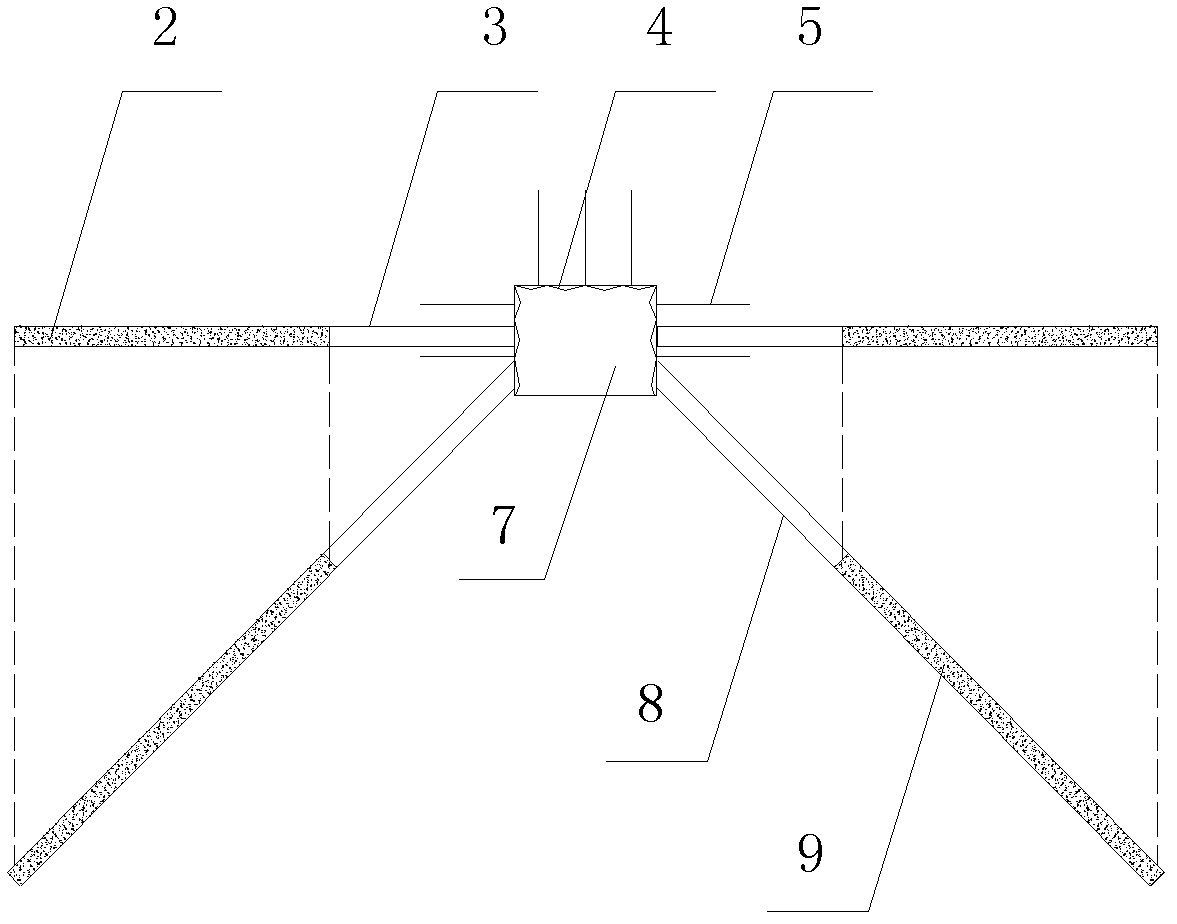
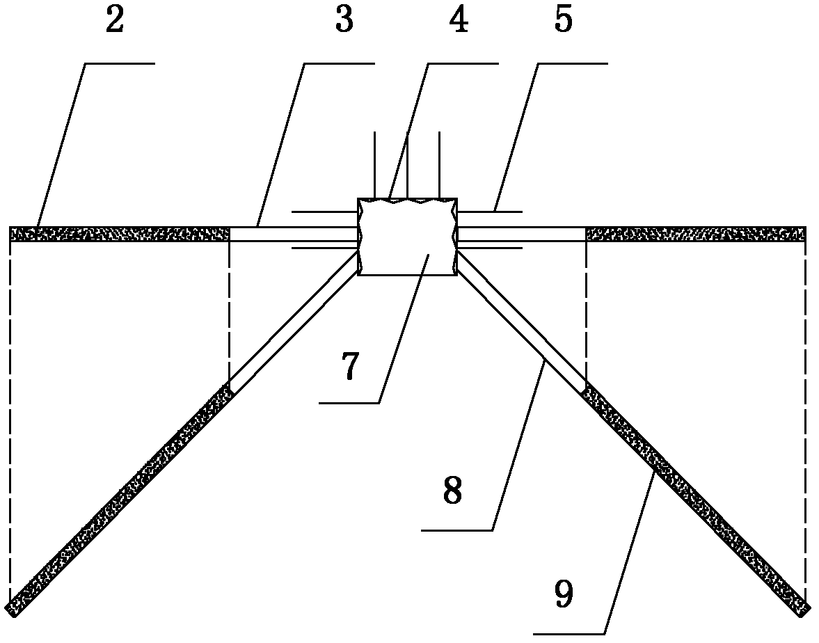
The invention discloses a method for controlling a laneway floor heave through deep-hole section blasting. The method comprises the following steps of: boring a combined blast hole incline and below two edges of a laneway and a base plate under strong support, and filling explosive to blast in a special section of the deep part of the blast hole to realize that the stresses of the special sections of the laneway edges and the base plate are transmitted to the deep parts of surrounding rocks. The invention has the beneficial effects that: a rock layer of the base plate of the laneway at the position is arranged under a stress environment with a lower level and the total deformation amount of the base plate is reduced by blasting and decompressing the special sections of the deep parts of the laneway edges and the base plate; simultaneously, the special sections are arranged in the deep parts of the surrounding rocks, thus the influence of the blasting on the completeness and the bearing capability of a surrounding rock structure in a shallow part is smaller, and the surrounding rock structure in the shallow part can still effectively prevent the deformation of the surrounding rocksin the deep parts. According to the method disclosed by the invention, the surrounding rocks in the deep part of the laneway are blasted, the surrounding rocks in the shallow parts are reinforced andare protected in completeness, both of aspects are organically combined, thus the amount of the laneway floor heaves is controlled. The method of the invention is simple and convenient to construct, is easy to handle, and has better control effect on the floor heaves and wide application prospect.

Description

technical field [0001] The invention relates to the technical field of coal mine safety, in particular to a method for controlling roadway bottom by deep hole section blasting. Background technique [0002] With the continuous increase of coal mining depth, the phenomenon of large deformation and damage to the surrounding rock of the roadway is becoming more and more serious, among which the problem of roadway bottom sag and floor impact is the most prominent. At present, the traditional method of controlling roadway floor is mainly to passively reinforce and support the floor, and limit the surface displacement of the floor. In fact, the main cause of the impact of the roadway floor and floor is the stress concentration of the surrounding rock. The active transfer and release of stress is to fundamentally solve the problem of roadway floor and floor impact. A few scholars have realized this problem and adopted blasting The pressure relief method is used to prevent and cont...

Claims


Application Information

Patent Timeline
IPC IPC(8): F42D1/00F42D3/04
Inventor 潘俊锋王书文毛德兵蓝航夏永学彭永伟陈法兵
Owner TIANDI SCI & TECH CO LTD
Learn More