
Windmill blade structure capable of altering actuated blade area automatically

A technology of blade structure and windmill, applied in the direction of engine, wind turbine, machine/engine, etc., can solve the problems of reducing the working efficiency of windward blades, unable to exert the effect of wind force to the limit, and reducing the driving efficiency of windmill.

Inactive Publication Date: 2014-07-30
田壁斌
View PDF11 Cites 3 Cited by
  • Summary
  • Abstract
  • Description
  • Claims
  • Application Information

AI Technical Summary

Problems solved by technology

[0003] Commonly used windmill blades are usually designed in a fixed shape. When it is in the windward state, it will drive the main shaft of the windmill to rotate due to the wind force. However, when it is in the leeward state, it will also produce a reaction force due to the wind force, reducing the windward The working efficiency of the blades reduces the driving performance of the windmill, and the effect of the wind cannot be exerted to the limit

Method used


Image

  • Windmill blade structure capable of altering actuated blade area automatically
  • Windmill blade structure capable of altering actuated blade area automatically

Examples


Embodiment Construction

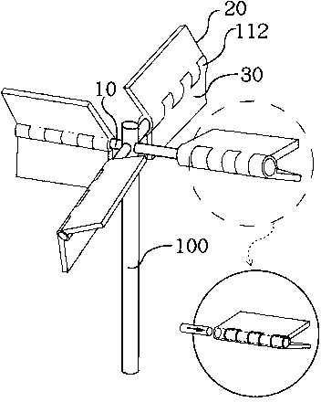
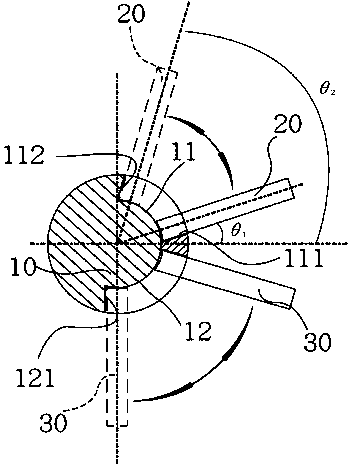
[0016] The present invention relates to a windmill blade structure, as shown in the first to second figures, it mainly includes a main shaft (10), the first end of the main shaft (10) is horizontally fixed on the windmill On the rotating shaft (100); an upper blade (20) and a lower blade (30) are respectively installed on the second end of the main shaft (10).

[0017] An upper arc-shaped groove (11) and a lower arc-shaped groove (12) are formed transversely at the second end of the main shaft (10). The bottom edge and the upper edge of the upper arc-shaped groove (11) are respectively provided with a lower stop part (111) and an upper stop part (112), wherein, the distance between the lower stop part (111) and the horizontal plane The included angle (θ1) is not less than 0 degrees; and the included angle (θ2) between the upper stop portion (112) and the horizontal plane is not greater than 90 degrees. The lower arc-shaped groove (12) has a lower stop portion (121), and the l...


PUM


Abstract

The invention provides a windmill blade structure which is capable of altering the actuated blade area automatically. The structure comprises a spindle the first end of which is horizontally fixed on the rotation shaft of a windmill, wherein the spindle is provided with a plurality of block parts properly distributed along the spindle; an upside blade and a downside blade are articulated with the spindle around which the blades are capable of swinging separately within an confined angle range from 5 to 90 degrees and from minus 15 to minus 90 degrees. The structure provided by the invention has the beneficial effects that the maximum wind power effect is obtained when the blades are completely opened automatically with a maximum actuated area at the position of the actuated blade sides facing to the wind; and meanwhile, a wind resistance effect is minimized when the blades are closed automatically with a minimum dragged area at the position of the drag blade sides (convex sides) facing to the wind.

Description

technical field [0001] The invention relates to a windmill blade structure, in particular to a windmill blade structure which can automatically reduce the windward area when in a leeward state and improve wind power utilization efficiency. Background technique [0002] Windmills have been the cheapest mechanical driving force since ancient times. With the rising tide of environmental protection awareness, they are also a source of green energy that people from all walks of life are flocking to. Therefore, how to maximize its utilization rate is a technical field that various companies are competing to study. [0003] Commonly used windmill blades are usually designed in a fixed shape. When it is in the windward state, it will drive the main shaft of the windmill to rotate due to the wind force. However, when it is in the leeward state, it will also produce a reaction force due to the wind force, reducing the windward The working efficiency of the blades reduces the driving ...

Claims


Application Information

Patent Timeline
Patent Type & Authority Patents(China)
IPC IPC(8): F03D3/06
CPCY02E10/74
Inventor 田壁斌
Owner 田壁斌
Learn More