
Subway tunnel advertisement lamp board self-powered control system

A control system and self-powered technology, applied in the field of power generation machinery, can solve the problems of demanding wind speed changes and load changes, lack of wind energy collection and utilization efficiency, affecting installation and dustproof effects, etc., and achieve strong anti-glare interference capabilities , high power density and reliability, and the effect of high wind utilization efficiency

Pending Publication Date: 2019-09-03
SOUTHWEST JIAOTONG UNIV
View PDF1 Cites 0 Cited by
  • Summary
  • Abstract
  • Description
  • Claims
  • Application Information

AI Technical Summary

Problems solved by technology

[0003] According to the search, there have been technologies that use tunnel wind energy to supply power to advertising lights. For example, the Chinese patent application No. 201521130018. Horizontal axis wind turbines can only obtain wind energy in one direction. At the same time, the fan structure of the device is too simple, the utilization rate of wind energy is low, and the overall structure of the device is scattered, which affects the installation and dustproof effect.
Another example is "a vertical axis wind power generation system utilizing wind energy in subway tunnels" disclosed in Chinese Patent Application No. 01220093939.3. type impeller, there is a problem that it cannot be started automatically, and the requirements for wind speed change and load change are relatively strict, so it is difficult to run smoothly and efficiently in the subway tunnel
The tunnel wind energy power supply system described in the above two patents can only convert wind energy into electrical energy to supply power for advertising light boards on the basis of traditional wind energy collection, which is still lacking in wind energy collection and utilization efficiency

Method used


Image

  • Subway tunnel advertisement lamp board self-powered control system
  • Subway tunnel advertisement lamp board self-powered control system
  • Subway tunnel advertisement lamp board self-powered control system

Examples


Embodiment Construction

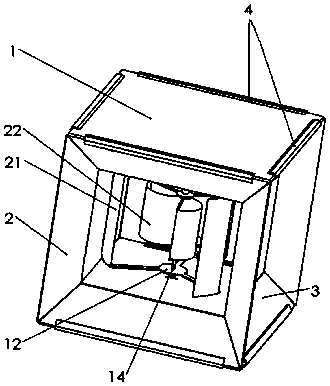
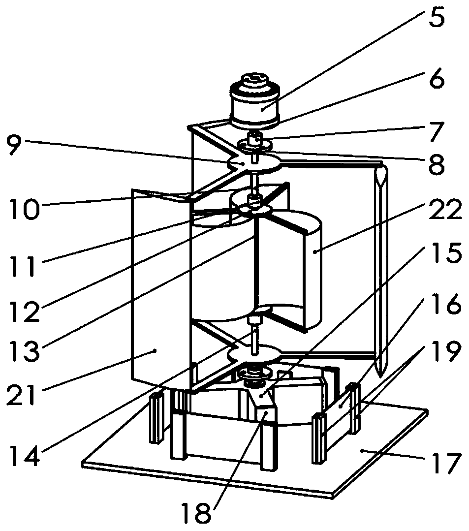
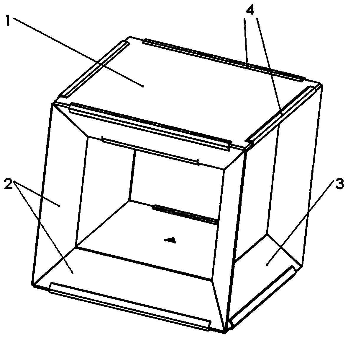
[0039] In the accessories, outer plate-1; inner plate-2; side plate-3; shell connector-4; generator-5; generator main shaft-6; coupling-7; A support-9; the first main shaft-10; overrunning clutch-11; the second support-12; the second main shaft-13; the third main shaft-14; magnet turret-15; ) base plate-17; magnet-18; piezoelectric plate baffle-19; turret bearing seat-20; lift type fan blade-21; resistance type fan blade-22.

[0040] see figure 1 , figure 2 , a subway tunnel advertising light board self-supply energy control system, including a storage battery used to provide electric energy for the subway advertising light board, the housing is composed of an inwardly contracted air inlet part, a constant flow cross-section part, and an outwardly expanding air outlet part; The wind energy and piezoelectric generating mechanism used for charging the storage battery are arranged in the housing:

[0041] The generator main shaft 6 below the generator 5 is connected to the fi...


PUM


Abstract

The invention discloses a subway tunnel advertisement lamp board self-powered control system. The system is characterized in that a power generation device is arranged in a shell, an electric generator is connected with a first main shaft through a coupling device, the first main shaft and a second main shaft are connected through an overrun clutch, the second main shaft and a third main shaft areconnected through the overrun clutch, and the third main shaft is connected with a rotating shaft of a magnet rotating frame; magnets are arranged on four rotating arms of the magnet rotating frame,the magnetic poles of the four magnets sequentially are N, S, N and S, and the magnets on four piezoelectric plates are located at a position at which the magnets on the four piezoelectric plates canact with the magnets on the rotating arms; and three lifting type fan blades are arranged on two second supports, the two second supports are arranged on the first main shaft and the third main shaft,three resistance type fan blades are arranged on the two second supports, and the two second supports are arranged on the second main shaft. According to the system, the wind energy is used for powergeneration through the electric generator and piezoelectric plates, and the generated power is used for supplying power for subway advertisement lamp boards, and the system has the characteristics ofbeing high in wind power utilization efficiency, high in power generation efficiency and the like.

Description

technical field [0001] The invention belongs to the technical field of power generation mechanical devices, in particular to a device for generating power by a generator utilizing tunnel piston wind energy and generating power by vibration of a piezoelectric sheet. Background technique [0002] With the consumption of fossil fuels such as natural gas and oil, as well as the resulting energy crisis and environmental pollution, the development and utilization of new, clean and safe renewable energy and the reduction of pollution emissions have become two major concerns of the world. focus. As a clean energy, wind energy has been paid more and more attention in our country. The subway tunnel piston wind is the wind energy generated when the subway passes through the tunnel. By collecting the piston wind and converting it into electrical energy, the consumption of unclean energy can be greatly reduced. At the same time, there are a large number of subway advertising light boar...

Claims


Application Information

Patent Timeline
IPC IPC(8): F03D9/11F03D9/46F03D3/00F03D3/06F03D3/04F03D13/20H02J7/32G09F13/00G09F13/04
CPCF03D9/11F03D9/46F03D3/005F03D3/061F03D3/0427F03D3/062F03D13/20H02J7/32G09F13/005G09F13/0413G09F13/0418Y02E10/728Y02E10/74Y02B10/30Y02E70/30
Inventor 张祖涛漆令飞郑超群曾晓辉何闻胡秉伦刘娟朱紫琦潘亚嘉
Owner SOUTHWEST JIAOTONG UNIV
Learn More