Connection assembly for connecting turbine housing to support housing and exhaust gas turbocharger

一种涡轮机壳体、支承壳体的技术,应用在发动机元件、燃气轮机装置、机器/发动机等方向,能够解决不能补偿、加剧壳体热膨胀、气体泄漏等问题,达到好密封效果、防止气体泄漏、实现稳定性的效果

Inactive Publication Date: 2011-12-14
IHI CHARGING SYST INT
View PDF8 Cites 0 Cited by
  • Summary
  • Abstract
  • Description
  • Claims
  • Application Information

AI Technical Summary

Problems solved by technology

thus, figure 1 A disadvantage of the prior art shown in is that different thermal expansions of the two housings occur due to different thermal expansion coefficients
[0009] Since the insulation 18 is positioned more axially toward the turbine casing 14 so that the seal assembly 20 is not centered with respect to the V-ribbon clamp 16 , at extreme temperature differentials due to differential thermal expansion of the casing, Causes a gap that cannot be adequately compensated, or even not compensated at all, by a V-ribbon clamp
The result may be gas leaks, exhaust gas may flow from the exhaust turbocharger into the environment
[0010] In addition, the different thermal expansion of the housings is exacerbated by improper positioning of the thermal insulation 18 which causes the turbine housing 14 to heat up more strongly than the support housing 12
[0011] In addition, this higher heat introduction may cause warping / bending of the surfaces of the insulation 18 that make contact in the seal assembly 20, which warping can cause gas leakage

Method used


Image

  • Connection assembly for connecting turbine housing to support housing and exhaust gas turbocharger
  • Connection assembly for connecting turbine housing to support housing and exhaust gas turbocharger
  • Connection assembly for connecting turbine housing to support housing and exhaust gas turbocharger

Examples


Embodiment Construction

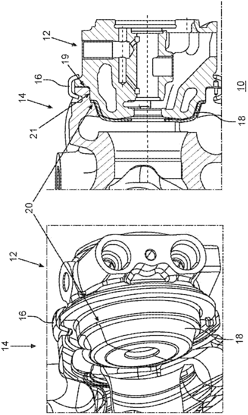
[0040]figure 1 Shown is a prior art connection assembly for connecting the turbine housing of an exhaust-gas turbocharger with a support housing, wherein the thermal insulation is formed by the support housing, the turbine housing and the thermal insulation The seal assembly is positioned in the axial direction towards the turbine housing and thus outside the connection, figure 2 A connection assembly is shown connecting the turbine housing of the exhaust-gas turbocharger with the support housing, wherein the seal assembly is positioned centrally with respect to the connection element and thus with respect to the housing. image 3 show figure 2 The connection assembly of , where the longitudinal section is located in another plane of the connection assembly, thus showing figure 2 Other aspects of connected components.

[0041] figure 2 A connecting assembly 30 is shown, in which the bearing housing 12 ′ and the turbine housing 14 ′ are connected to one another by means ...


PUM


Abstract

In a connection assembly of a turbine housing to a bearing housing of an exhaust gas turbocharger and to an exhaust gas turbocharger, wherein the turbine housing and the bearing housing are centered relative to each other and connected to each other in the region of a connection joint including a sealing assembly with a heat shield disposed between the turbine housing and the bearing housing, at least one cutout is provided in the heat shield for accommodating a centering means by way of which the turbine housing and the bearing housing are directly centered relative to one another.

Description

technical field [0001] The invention relates to a connection arrangement for connecting a bearing housing of an exhaust-gas turbocharger to a turbine housing according to the preamble of claim 1 and to an exhaust-gas turbocharger according to the preamble of claim 10 device. Background technique [0002] Such connection assemblies are known and available in figure 1 shown in . [0003] figure 1 A connection arrangement 10 for connecting a turbine housing 14 of an exhaust-gas turbocharger to a support housing 12 is shown. Here, the turbine housing 14 is centered on the bearing housing 12 by means of a centering flange 21 . [0004] If the two housings are connected by means of a V-shaped clamping strip 16 , a connecting seam 19 to be sealed will of course be formed. [0005] The sealing of the connecting joint 19 is achieved in that the turbine housing 14 and the support housing 12 together with the thermal insulation 18 form a sealing assembly 20 , thereby preventing th...

Claims


Application Information

Patent Timeline
Patent Type & Authority Applications(China)
IPC IPC(8): F02C6/12F02C7/24
CPCF05B2230/606F05D2220/40F02C6/12F05D2230/642F05B2220/40F02C7/24
Inventor J·S·德利茨
Owner IHI CHARGING SYST INT
Why Eureka
Try Eureka