
Device for accurately controlling film to advance for microfilm camera

A technology for microfilm and camera, which is applied to electromechanical devices, printing devices, printing equipment, etc., can solve the problems of inability to realize exposure imaging of digital image microfilm cameras, hindering popularization and application, and short life of key components, etc. The requirements of high-resolution technical indicators, stable and reliable transmission synchronization, and stable and reliable noise

Inactive Publication Date: 2013-04-17
TIANJIN IAT SCI & TECH
View PDF3 Cites 0 Cited by
  • Summary
  • Abstract
  • Description
  • Claims
  • Application Information

AI Technical Summary

Problems solved by technology

[0002] At present, the technical method of using digital image microfilm cameras on the market is to expose images on microfilm by laser scanning, so there are problems such as complex technology, high equipment cost, short life of key components, and high maintenance costs, which hinder popularization and application.
[0003] Using LCD and LCOS liquid crystal imaging technology to expose and image on microfilm has mature technology, low cost, and long life. There is a large gap between the resolution index and the resolution technical index of digital image microfilm camera equipment. Therefore, the exposure and imaging of digital image microfilm camera cannot be achieved by using the existing LCD panel or LCOS panel one-time display exposure method. technical indicators

Method used

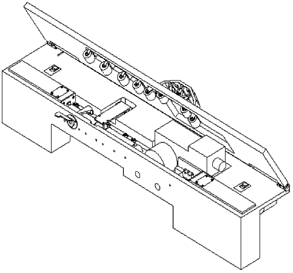
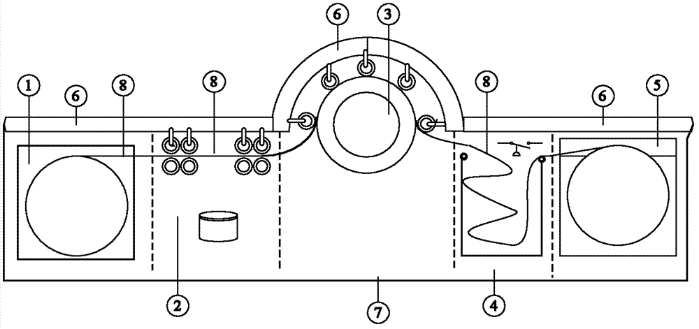
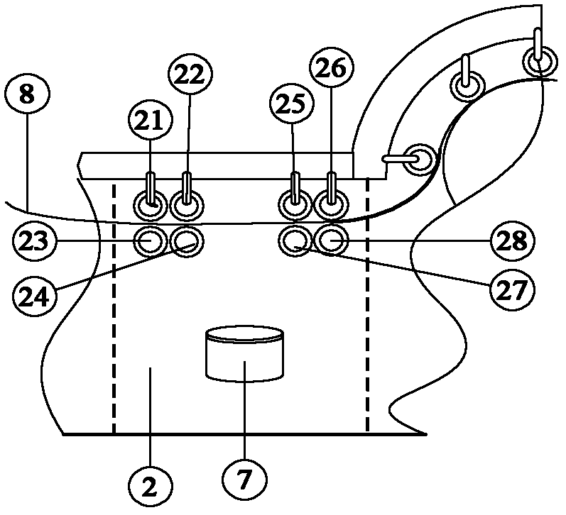

Image

  • Device for accurately controlling film to advance for microfilm camera
  • Device for accurately controlling film to advance for microfilm camera
  • Device for accurately controlling film to advance for microfilm camera

Examples


Embodiment Construction

[0017] Below in conjunction with accompanying drawing and preferred embodiment, specific implementation, structure, feature are described in detail as follows:

[0018] figure 1 and 2 As shown, the device of the present invention includes an original film box 1, a film exposure area 2, a precise film driving mechanism 3, a film receiving buffer zone 4, a film receiving box 5, a mechanism upper cover 6 and a film traveling mechanism base 7, wherein the original film box 1 and the receiving box 5 are airtight closures made of metal materials with the same structure, which can ensure the safety of the film stored inside and no light leakage. Before the system works, install the original film box 1 and the receiving box 5 with microfilms to the corresponding position. The original film box 1 is used as a cassette for storing the film before exposure, and transports the film to the exposure area 2 smoothly at any time.

[0019] image 3 It is a structural schematic diagram of t...


PUM


Abstract

The invention discloses a device for accurately controlling a film to advance. The device comprises a mechanism pedestal and a mechanism top cover, wherein an original film box, a film exposure area, a precise film advance driving mechanism, a film taking buffer area and a film taking box are sequentially arranged in the pedestal; a rotor wheel group is arranged in the exposure area; the upper wheel of the rotor wheel group is fixed in the mechanism top cover; the lower wheel of the rotor wheel group is fixed to the pedestal; the precise film advance driving mechanism comprises a stepping motor, a worm and a worm wheel which are arranged on the pedestal; the worm is driven to rotate by the stepping motor; the worm wheel rotates synchronously; the worm wheel and a driving wheel are coaxially arranged; a film pressing wheel group is arranged in the semi-circumferential surface of the mechanism top cover which is positioned above the driving wheel; the film taking box and a film taking detecting switch are arranged in the film taking buffer area; a film taking motor is arranged in the film taking box; and the stepping motor, the film taking detecting switch and the film taking motor are controlled by a control system singlechip. By using the device for accurately controlling the film to advance, the entire split image can be exposed to proper positions on the film for several times, and the image which is exposed for several times can be spliced in a seamless mode.

Description

technical field [0001] The invention relates to a device for precisely controlling film travel by using electromechanical technology, in particular to a device for precisely controlling film travel for computer image output to a microfilm camera. Background technique [0002] At present, the technical method of using digital image microfilm cameras on the market is to expose images on microfilm by laser scanning, so there are problems such as complex technology, high equipment cost, short life of key components, and high maintenance costs, which hinder popularization and application. [0003] Using LCD and LCOS liquid crystal imaging technology to expose and image on microfilm has mature technology, low cost, and long life. There is a large gap between the resolution index and the resolution technical index of digital image microfilm camera equipment. Therefore, the exposure and imaging of digital image microfilm camera cannot be achieved by using the existing LCD panel or L...

Claims


Application Information

Patent Timeline
Patent Type & Authority Patents(China)
IPC IPC(8): G03B27/52H02K37/24
Inventor 靳张铝李迎孙小金刘喜章
Owner TIANJIN IAT SCI & TECH
Learn More