
A water filter device

A filter screen and water inlet pipe technology, which is applied in water/sewage treatment, water/sludge/sewage treatment, magnetic field/electric field water/sewage treatment, etc., can solve the problem of unsatisfactory treatment capacity and filtering effect, and small water spray volume of road rollers , can not spray water pump and other problems, to achieve the effect of convenient and thorough maintenance and cleaning, long maintenance cycle and convenient work

Inactive Publication Date: 2011-12-14
SINOMACH CHANGLIN CO LTD
View PDF8 Cites 5 Cited by
  • Summary
  • Abstract
  • Description
  • Claims
  • Application Information

AI Technical Summary

Problems solved by technology

The water tank made of stainless steel or plastic material in the road roller is generally small in volume and has the problem of small water storage. For example, the cavity in the steel frame is used to form the water tank. Although the volume of the water tank increases, due to the water tank wall It will rust, and the falling rust will block the nozzle. In addition, due to the limitation of the construction site conditions of the road roller, the water taken may contain other non-ferromagnetic impurities, which will also block the nozzle, so the amount of water sprayed by the road roller will occur during the working process. Too small or even unable to spray water and damage to the water pump, etc.
[0004] If the above two filters are applied to the water spray system of the road roller, the water treatment capacity and filtering effect will not be ideal.

Method used


Image

  • A water filter device
  • A water filter device
  • A water filter device

Examples


Embodiment 1

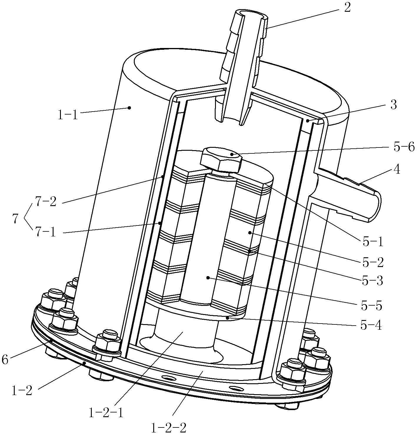
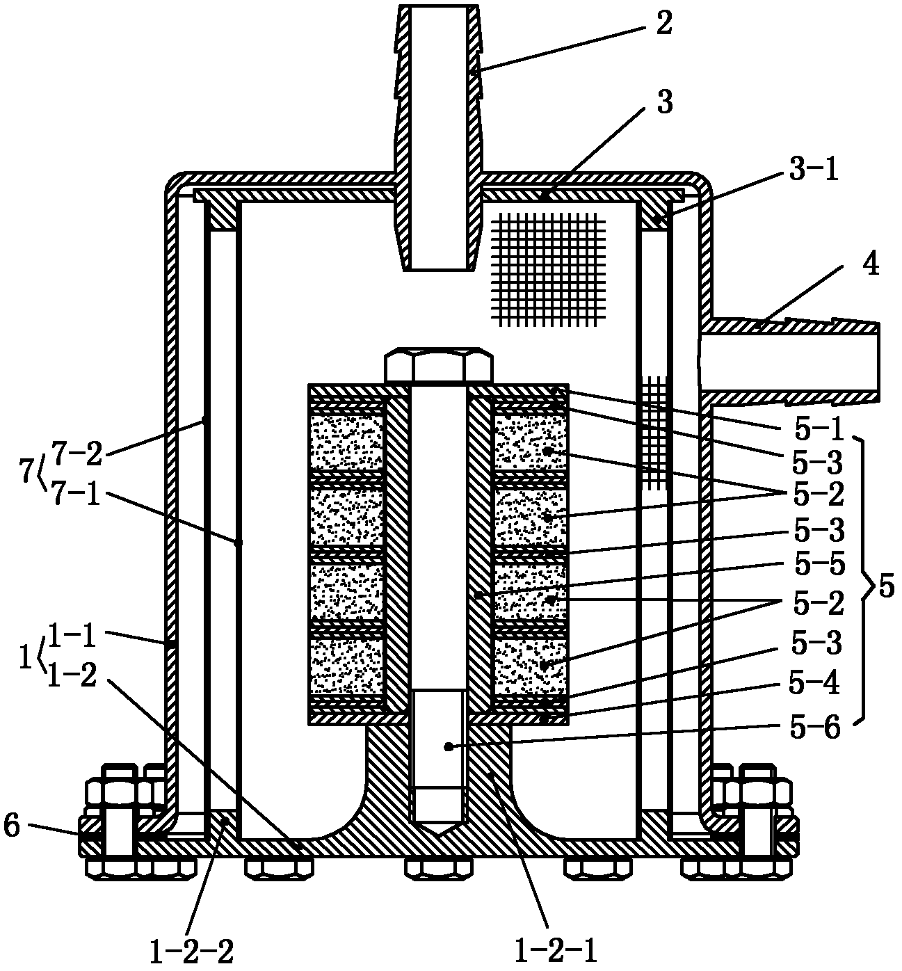
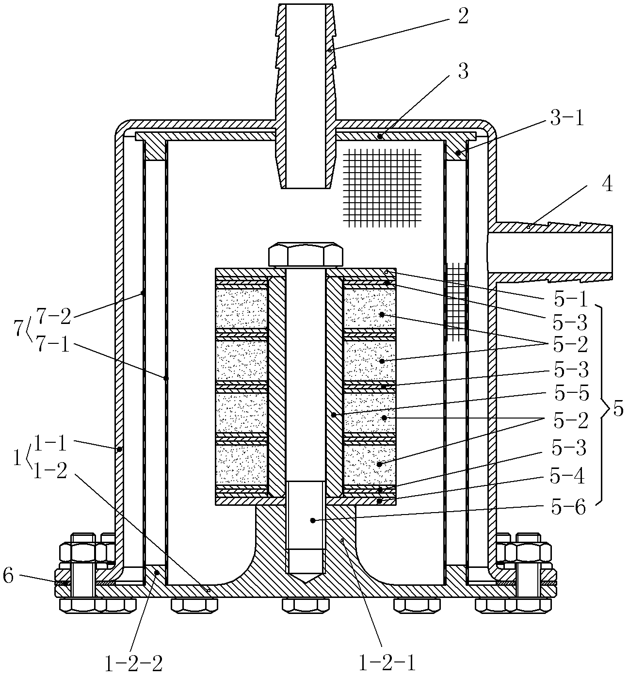
[0015] See the accompanying drawings, this embodiment includes a housing 1, the housing 1 is formed by connecting the cover shell 1-1 and the base 1-2 with bolts, a sealing ring 6 is arranged between the cover shell 1-1 and the base 1-2, and the cover The top center of the shell 1-1 is provided with a water inlet, and the water inlet is provided with a water inlet joint 2, and the water inlet joint 2 extends downward, and its lower part is in the cover shell 1-1. A water outlet is provided on the upper part of the side wall of the cover shell 1-1, and a water outlet pipe joint 4 is provided on the water outlet. The base 1-2 is provided with a central boss 1-2-1 and an annular boss 1-2-2 around the central boss 1-2-1, and the central boss 1-2-1 is provided with an axial The threaded hole of the central boss 1-2-1 is equipped with a combined magnetic core 5.

[0016] The combined magnetic core 5 includes a top plate 5-1, a supporting plate 5-4, a hollow column 5-5, a fixing bol...


PUM


Abstract

The invention provides a water filtering apparatus, which comprises a casing, the casing is formed by connection of a cover casing and a base, the top of the cover casing is provided with a water inlet, a water outlet is provided on the upper part of a sidewall of the cover casing, a central boss is provided on the base, a combined magnetic core is arranged on the central boss, the combined magnetic core comprises a top board, a supporting plate, a hollow column, fixed bolts and a plurality of permanent magnets sleeved on the hollow column, and the polarities of adjacent permanent magnets arereverse, the hollow column is placed between the top board and the supporting plate, the fixed bolts are screwed into the central screwed hole of the central boss on the base through a central aperture on the top board, the hollow column and a central aperture on the supporting plate of the combined magnetic core for integrally fixing the combined magnetic core on the base, filter screens placed between an inner end face of the cover casing and the base are provided around the combined magnetic core. According to the invention, a plurality of permanent magnets are employed to form a multipolar magnetic field which has a large adsorption area and strong adsorption capability to the ferromagnetism impurity, and because the area of the filter screen is large, the invention achieves the purpose that the water treatment amount is large and the filtering effect is good.

Description

technical field [0001] The present invention relates to a water filtering device. Background technique [0002] Chinese patent application number is 90210215 utility model patent application specification discloses a kind of mesh type magnetic filter, and it is made up of parts such as cylinder body and oil filtering magnetic core, and its characteristic is the oil filtering magnetic core that is made up of six magnetic columns, each The first magnetic column is formed by stacking several magnetic blocks according to the opposite polarity. With the screw as the center, two magnetic columns are spaced at an angle of 60°, and the two magnetic columns are arranged according to the opposite polarity. The above-mentioned net-type magnetic filter is used for the purification of insulating oil for transformers and the treatment of other high-cleanliness oils. The space for storing impurities is small, the processing capacity is small, and frequent maintenance is required. Chines...

Claims


Application Information

Patent Timeline
IPC IPC(8): C02F1/00C02F1/48
CPCB03C1/0332B03C1/286B03C2201/18B03C2201/28
Inventor 蒋惠锦朱武强陈栋
Owner SINOMACH CHANGLIN CO LTD
Learn More