Method for defining shared risk link group in optical transmission system

A technology for sharing risk links and optical links, applied in the field of limiting shared risk link groups in optical transmission systems

Inactive Publication Date: 2011-12-07
XIEON NETWORKS SARL
View PDF3 Cites 3 Cited by
  • Summary
  • Abstract
  • Description
  • Claims
  • Application Information

AI Technical Summary

Problems solved by technology

The difficulty with this approach is to identify SRGs shorter than 100 miles that o...

Method used


Image

  • Method for defining shared risk link group in optical transmission system
  • Method for defining shared risk link group in optical transmission system
  • Method for defining shared risk link group in optical transmission system

Examples


Embodiment Construction

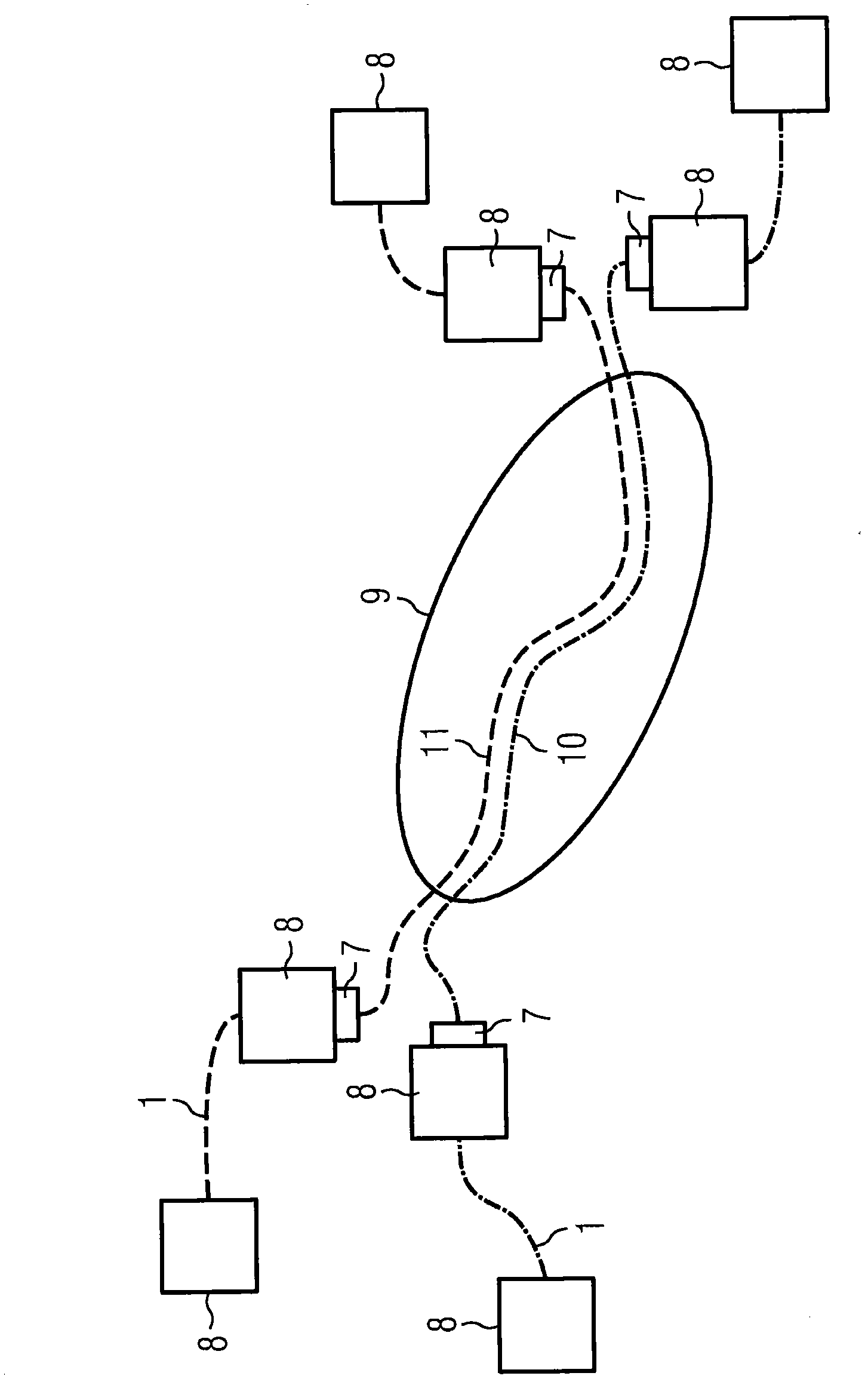
[0019] figure 1 A part of an optical transmission system with two optical links 1 is shown in , where parts 10 and 11 of the two links are wired in parallel, so they are part of a shared risk group 9 . Some network elements 8 are equipped with OTDR measurement devices 7 . If the OTDR measurements of links 10 and 11 show the same SOP characteristics, they are judged to be non-disjoint, and thus they are in the same shared risk link group.

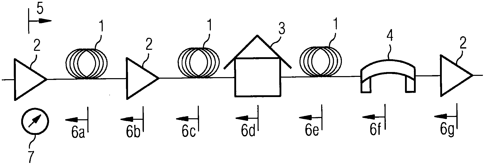
[0020] figure 2 The hinge model for sample optical link 1 is shown in . This link is routed between optical amplifiers 2 . There may be additional amplifiers 2, service huts (huts) 3 and bridges 4 on this link. On the optical link, the light rays of the test signal 5 are scattered back from all these network elements or "hinges", these being indicated by arrows 6a to 6e. The backscattered light is analyzed in OTDR measurement 7. The measurements are used to establish a fingerprint of the optical link. This measurement is even more im...


PUM


Abstract

A method defines shared risk link groups in optical transport systems, in which two optical links sharing at least one single point of failure are considered to be non-disjoint. For each optical link there is measured and recorded a polarization state characteristic and two links having the same characteristic are judged to be non-disjoint and to be in the same shared risk link group.

Description

technical field [0001] The present invention relates to a method of defining a shared risk link group in an optical transmission system, wherein two optical links sharing at least one single point of failure are considered non-failure Intersect (non-disjoint). Background technique [0002] Most telecommunication services require highly available networks. End-to-end availability of 0.99999 (five nines) is defined in many service level agreements today. To obtain these high-availability end-to-end connections, resiliency mechanisms for rerouting traffic are deployed around failed network elements. Failure of a network element is caused by some cause such as a line cut, fire, natural disaster or misconfiguration. [0003] In optical transport networks, particularly high availability can only be ensured by means of redundant optical links. These must be disjoint, meaning these do not share elements in the net and cannot be routed in parallel. Information about non-disjoint...

Claims


Application Information

Patent Timeline
IPC IPC(8): H04B10/08H04B10/079
CPCH04B10/07951H04B10/071
Inventor C·格鲁贝尔M·霍夫曼C·默克勒H·罗德D·舒普克
Owner XIEON NETWORKS SARL
Why Eureka
Try Eureka