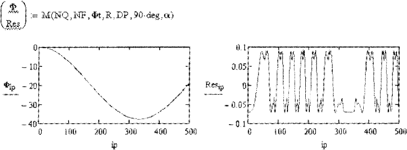
Phase Shift Interference in Vibration Fields

A phase-shift interference and phase-shift technology, applied in instruments, measuring devices, optics, etc., to solve problems such as surface profile errors and uneven scanning motion.

Active Publication Date: 2011-12-07
ZYGO CORPORATION
View PDF7 Cites 6 Cited by
  • Summary
  • Abstract
  • Description
  • Claims
  • Application Information

AI Technical Summary

Problems solved by technology

[0007] If the scanning motion is not uniform, the measured surface profile will be wrong
Unfortunately, scanning motion in PSI tends to be uneven

Method used


Image

  • Phase Shift Interference in Vibration Fields
  • Phase Shift Interference in Vibration Fields
  • Phase Shift Interference in Vibration Fields

Examples


Embodiment Construction

[0061] As used herein, the term "comprise" and variations thereof are used synonymously with the term "comprising" and variations thereof, and are open, non-limiting terms.

[0062] There are many possible implementations of the present invention, too numerous to describe here. Some possible embodiments that are presently preferred are described below. However, it cannot be overemphasized that what is described here is an embodiment of the invention rather than a description of the invention, which is not limited to the detailed embodiments described in this section, but rather is described in the broader terms of the claims.

[0063] phase shift interferometer

[0064] The present invention relates to phase shifting interferometers. figure 1 An example of a phase-shifting interferometric system 50 for obtaining an interferometric signal is shown, comprising an interferometer 51 and a processor 52 (eg, an automated computer-controlled system). The measurement system 50 is...


PUM


Abstract

The present invention provides a phase-shifting interferometry (PSI) method and corresponding system including: (i) recording an interferogram for each phase in a sequence of phases between test light reflected from a test surface and reference light reflected from a reference surface, the interferograms defining an interferometry signal for each of different transverse locations of a cavity defined by the test and reference surfaces; (ii) calculating an initial phase map for the cavity based on at least some of the recorded interferograms; (iii) calculating an estimate for each of at least some of the phase shift increments based on the initial phase map and at least some of the recorded interferograms; and (iv) calculating an improved phase map based on the calculated estimates for the phase shift increments and at least some of the recorded interferograms.

Description

technical field [0001] The present invention relates to phase shifting interferometry methods and related systems. Background technique [0002] Interferometric optics techniques are widely used to measure surface topography, optical thickness, flatness, and other geometric and refractive index properties of precision optical components, such as glass used in lithographic photomasks substrate. [0003] For example, to measure the surface profile of a measurement surface, an interferometer may be used to combine a measurement wavefront reflected from the measurement surface with a reference wavefront reflected from a reference surface to form an optical interference pattern. The spatial variation in the intensity profile of the optical interference pattern corresponds to the phase difference between the combined measurement and reference wavefronts, which phase difference is caused by the profile variation of the measurement surface relative to the reference surface. The co...

Claims


Application Information

Patent Timeline
Patent Type & Authority Applications(China)
IPC IPC(8): G01B9/02G01B11/24G01B11/02G02B27/14G02B26/08
CPCG01B9/02057G01B11/2441G01B9/02087G01B9/02077G01B9/02048G01B9/02079G01B9/02G01B11/24G01B11/02
Inventor 莱斯利.L.德克
Owner ZYGO CORPORATION
Why Eureka
Try Eureka