
New tail cap flashlight

A tail cover and flashlight technology, which is applied in the field of new tail cover flashlights, can solve the problems of unstable battery contact, easy damage to human hands, and easy wrinkling of edges, and achieves low production cost, simple structure, and fewer forming processes. Effect

Inactive Publication Date: 2011-12-07
顾兰如
View PDF0 Cites 1 Cited by
  • Summary
  • Abstract
  • Description
  • Claims
  • Application Information

AI Technical Summary

Problems solved by technology

This kind of old-style movable top electric frame has many processing procedures, and the top of the rolled edge is easy to wrinkle, so the contact with the battery is not smooth, and the gap is not smooth, which is easy to damage the hands

Method used


Image

  • New tail cap flashlight
  • New tail cap flashlight
  • New tail cap flashlight

Examples


Embodiment Construction

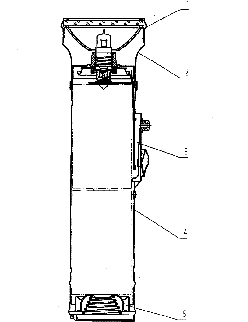
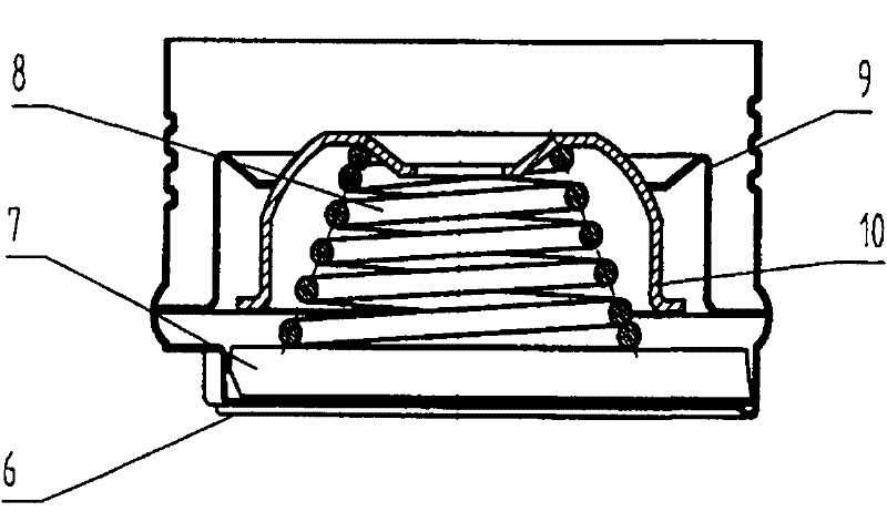
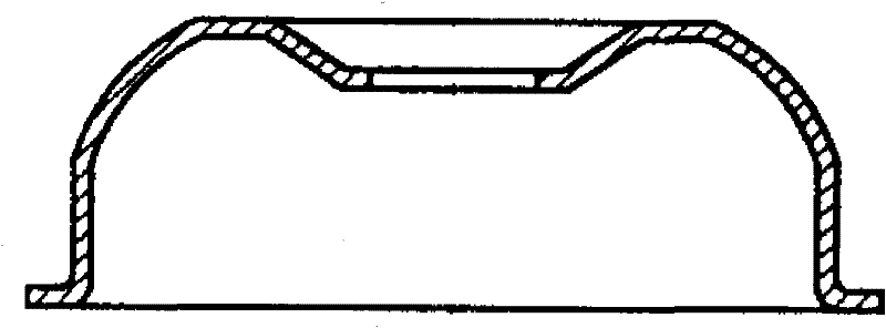
[0014] like Figure 1-4 As shown, a novel tail cap flashlight described in the embodiment of the present invention includes a head cap 1, a barrel neck 2, a switch portion 3, a barrel body 4 and a tail cap 5, and the tail cap 5 includes a tail cap 6, film 7, tail spring 8, fixed top electric frame 9, movable top electric frame 10, the movable top electric frame 10 of tail cover portion 5 is the disc structure that the center has aperture, and movable top electric frame 10 is movable and fixed on the fixed In the top electric frame 9, the disc-shaped bottom surface of the movable top electric frame 10 is in contact with the tail spring 8, and is pressed against the annular opening at the top of the fixed top electric frame 9, so that it can expand and contract in the fixed top electric frame 9 following the tail spring 8, To ensure good contact with the battery negative.


PUM


Abstract

The invention relates to a new flashlight with a tail cover, which includes a head cover, a barrel neck, a switch part, a barrel body and a tail cover. The top electric frame is movably sleeved in the fixed top electric frame, and its disc-shaped bottom surface is in contact with the tail spring, and is pressed against the ring opening at the top of the fixed top electric frame, and can expand and contract in the fixed top electric frame with the top spring. The invention has the beneficial effects of simple structure, beautiful appearance, practicality, less forming process and low production cost.

Description

technical field [0001] The invention relates to a novel tail cap flashlight. Background technique [0002] The barrel tail cover part of the existing flashlight includes a tail cover, a film, a tail spring, a fixed top electric frame, and a movable top electric frame. Wherein the movable top electric frame is a cylindrical seat with two gaps, and its top contacts the negative pole of the battery. This kind of old-style movable top electric frame has many processing procedures, and the top of the rolled edge is easy to wrinkle, so the contact with the battery is not stable, and the gap is not smooth, which is easy to damage the hands. Contents of the invention [0003] The purpose of the present invention is to provide a new tail cap flashlight, which has beautiful shape, stable contact with the battery, reduces the forming process, smooth surface and does not hurt hands, and overcomes the unstable contact with the battery in the existing products, which is easy to hurt ha...

Claims


Application Information

Patent Timeline
Patent Type & Authority Applications(China)
IPC IPC(8): F21L4/00F21V23/06
Inventor 顾兰如
Owner 顾兰如
Learn More