
Arrangement structure of transmission gear shaft system

A technology for arranging structure and gear shaft, applied in the direction of gear transmission, belt/chain/gear, transmission, etc., can solve the problems of unreasonable arrangement of gear shaft, unbalanced arrangement, small installation space of synchronous joint device, etc. The effect of reasonable internal space layout, balanced layout and large layout space

Inactive Publication Date: 2011-12-07
GIF RES CENT CHINA
View PDF4 Cites 0 Cited by
  • Summary
  • Abstract
  • Description
  • Claims
  • Application Information

AI Technical Summary

Problems solved by technology

[0004] However, the arrangement of the gear shafting of the existing six-speed gearbox is affected by many factors: the matching of the ratio, the matching of the center distance, the limitation of space, the space of the synchronous engagement device and the gear, the axial size, and the balance of the force etc., so that the arrangement of its gear shafting is mostly unreasonable. For example, Japanese Patent No. 4382973 disclosed a manual gearbox on October 2, 2009, which realized six-speed manual transmission through the shafting arrangement of the gears. However, the The shift sequence of the third and fourth gears of the manual transmission is inconsistent with the first, second, fifth and sixth gears, and an additional shift conversion mechanism is required to realize it. The installation space of the synchronous engagement device is small and the layout is unbalanced

Method used


Image

  • Arrangement structure of transmission gear shaft system
  • Arrangement structure of transmission gear shaft system

Examples


Embodiment Construction

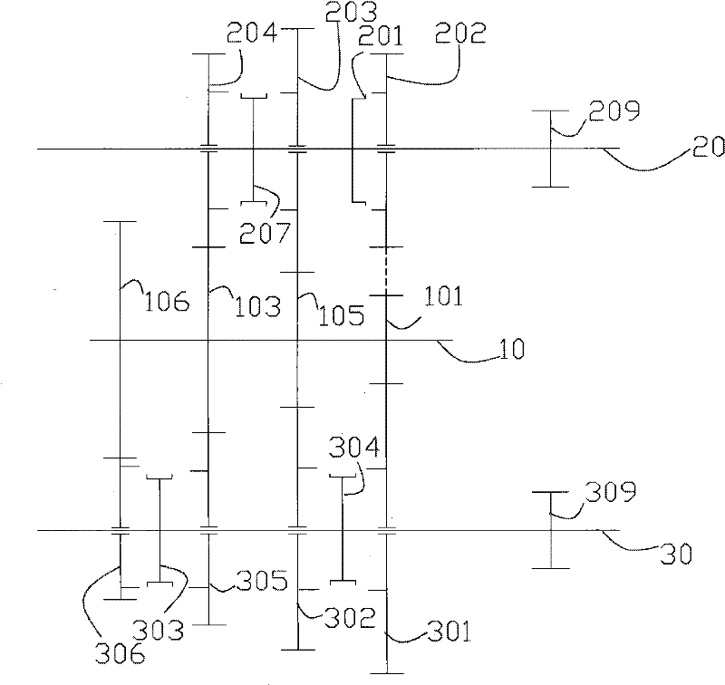
[0021] Such as figure 1 As shown, in the best embodiment of the layout structure of the manual gearbox gear shaft system of the present invention, an input shaft 10 is arranged in the manual gearbox, and the first output shaft 20 and the The second output shaft 30, the input shaft 10 is fixedly provided with a driving gear 101 for first gear, a driving gear for second and third gears 105, a driving gear for fourth and fifth gears 103 and a driving gear for sixth gear 106.

[0022] A reverse gear 202 , a third gear driven gear 203 and a fourth gear driven gear 204 are sheathed on the first output shaft 20 . The third gear driven gear 203 meshes with one end of the second and third gears 105, and can be driven to rotate by the second and third gears 105; the fourth gear driven gear 204 meshes with one end of the fourth and fifth gears 103, and can Driven by the fourth and fifth gears 103 to rotate. In addition, the first output shaft 20 is also provided with a first main and s...


PUM


Abstract

The invention relates to an arrangement structure of a gearbox gear shaft system, which includes an input shaft, two output shafts parallel to the input shaft and located on both sides of the input shaft, a driving gear is fixed on the input shaft, and various gears are sleeved on the output shaft. Driven gears, the driven gears of each gear are meshed with the driving gears of each gear, wherein, the fourth gear driven gear on the first output shaft and the fifth gear driven gear on the second output shaft are simultaneously connected with the fourth and fifth gears on the input shaft. The driving gear of the first gear meshes, that is, the fourth and fifth gears share one input gear, the second gear driven gear on the second output shaft and the third gear driven gear on the first output shaft mesh with the second and third gears at the same time, that is, the second and third gears Sharing one input gear, the reverse gear engagement device is mounted on the output shaft. Through the above structure, the internal space is reasonably arranged, the synchronous coupling device has enough installation space, and at the same time, the axial positions are roughly the same, the structural layout is balanced, and the axial distance is short.

Description

technical field [0001] The invention relates to an arrangement structure of a gearbox gear shaft system, in particular to a gear shaft arrangement scheme of a six-speed manual gearbox. Background technique [0002] In the early 1990s, the five-speed gearbox quietly emerged. Major car brands, including Mercedes-Benz, Mitsubishi, Honda, Santana, etc., have successively launched models equipped with five-speed gearboxes. Generally speaking, the fifth gear is generally the second overdrive gear, which reduces the variable transmission ratio and increases the speed of the vehicle. This is the new requirement of the user for the performance of the car after the expressway became popular in China at that time. Before long, the market developed such that cars with five-speed transmissions became mainstream. The structural principle of most five-speed gearboxes is to realize the speed change by the direct meshing of the input shaft and the output shaft gear. [0003] The six-speed...

Claims


Application Information

Patent Timeline
IPC IPC(8): F16H3/085
Inventor 马丁秦相
Owner GIF RES CENT CHINA
Learn More