
3D Pose Measurement Method of Object Based on Geometric Constraints

A technology of 3D attitude and geometric constraints, which is applied in the field of 3D attitude measurement of objects based on geometric constraints, and can solve problems such as special requirements for the geometric shape of feature points, a large number of feature points for pose calculation, and complex calculation processes, etc.

Inactive Publication Date: 2011-11-30
TIANJIN UNIV
View PDF2 Cites 17 Cited by
  • Summary
  • Abstract
  • Description
  • Claims
  • Application Information

AI Technical Summary

Problems solved by technology

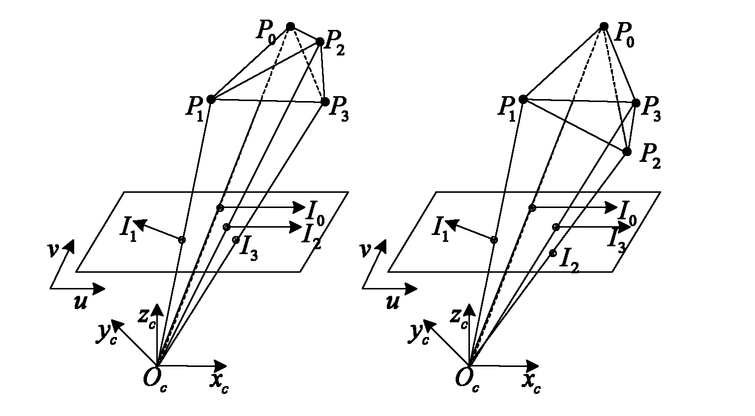
[0003] At present, most of the methods for measuring the three-dimensional pose of an object are to directly solve the rotation and translation matrix representing the pose of the object. This method generally faces two problems: 1. The number of feature points for pose calculation is too large, which leads to a complicated calculation process. ;2 There are special requirements for the geometric shape of the feature points in the solving process; here, the camera coordinate system is used as an intermediary, using 4 non-coplanar feature points, firstly solve the coordinates of the positioning feature points in the camera coordinate system, and then according to the feature The coordinates of the point in the camera coordinate system can be used to obtain the rotation and translation matrix of the object, and then the pose of the object can be obtained

Method used


Image

  • 3D Pose Measurement Method of Object Based on Geometric Constraints
  • 3D Pose Measurement Method of Object Based on Geometric Constraints
  • 3D Pose Measurement Method of Object Based on Geometric Constraints

Examples


Embodiment Construction

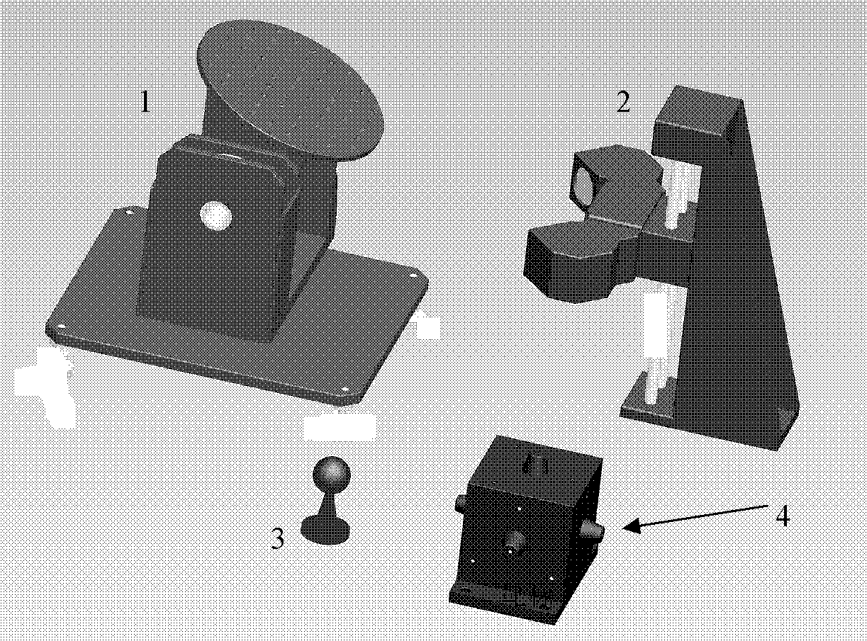
[0035] measurement system such as figure 1 As shown, the system consists of a sigma two-dimensional turntable, two cameras, and a target for measurement. The camera is fixed on the support frame and the position of the camera is adjusted according to the height of the turntable. The measurement target is a cube except the bottom surface. There are 4 non-coplanar infrared LEDs on each plane as the positioning feature points. The two-dimensional turntable drives the target to deflect. , Pitch two degrees of freedom movement, when using a single camera to shoot positioning feature points for pose calculation, in order to avoid the blind area of ​​shooting, but also to achieve the calibration of the two-dimensional turntable rotation axis, two cameras can be used from different angles Shoot location markers. The computer sends signals to the control box of the turntable through the serial port to control the movement of the turntable.

[0036] The coordinates of feature points i...


PUM


Abstract

The invention relates to electroencephalo-graph and vision detection and the measurement of a three-dimensional attitude of an object. In order to meet the requirement of intelligent, rapid, high-precision and low-cost detection of the three-dimensional attitude of the object in reality, the technical scheme is that: a geometric constraint-based method for measuring a three-dimensional attitude of an object is realized by means of a sigma two-dimensional turntable, two cameras, camera supporting frames, a measuring target and a computer; the two cameras are respectively fixed on the respective supporting frame and the positions of the cameras are adjusted according to the height of the turntable; and four non-coplanar infrared light-emitting diodes (LEDs) on each plane of the measuring target serve as positioning characteristic points, so that the two-dimensional turntable drives the target to make deflecting and pitching motions in two degrees of freedom. The method is realized by resolving the coordinate values of the characteristic points under a camera coordinate system according to geometric constraint formed by a spatial geometric shape of connecting lines of the characteristic points and the coordinate values of the characteristic points on a charge coupled device (CCD) image surface on the basis of the four non-coplanar characteristic points. The method is mainly applied to measuring the three-dimensional attitude of the object.

Description

technical field [0001] The invention relates to a visual detection technology and a three-dimensional attitude measurement of an object, in particular to a method for measuring a three-dimensional attitude of an object based on geometric constraints. Background technique [0002] The position and attitude measurement of objects has important application value in three-dimensional attitude measurement technology in aerospace, automobile four-wheel alignment, light pen measurement technology, helmet aiming and positioning system, underwater robot hovering and positioning, etc. Compared with magnetic field-based pose measurement methods, machine vision methods have been widely studied because they are not disturbed by electromagnetic fields. [0003] At present, most of the methods for measuring the three-dimensional pose of an object are to directly solve the rotation and translation matrix representing the pose of the object. This method generally faces two problems: 1. The n...

Claims


Application Information

Patent Timeline
Patent Type & Authority Applications(China)
IPC IPC(8): G01C11/00G01C11/02
Inventor 孙长库张子淼宋佳王鹏
Owner TIANJIN UNIV
Learn More