seat belt retractor

A winding device, a technology for seat belts, used in car seat belts, belt tensioners, transportation and packaging, etc.

Inactive Publication Date: 2011-11-30
KK TOKAI RIKA DENKI SEISAKUSHO
View PDF6 Cites 1 Cited by
  • Summary
  • Abstract
  • Description
  • Claims
  • Application Information

AI Technical Summary

Problems solved by technology

This restricts the rotation of the spool in the extraction direction

Method used


Image

  • seat belt retractor
  • seat belt retractor
  • seat belt retractor

Examples


Embodiment approach

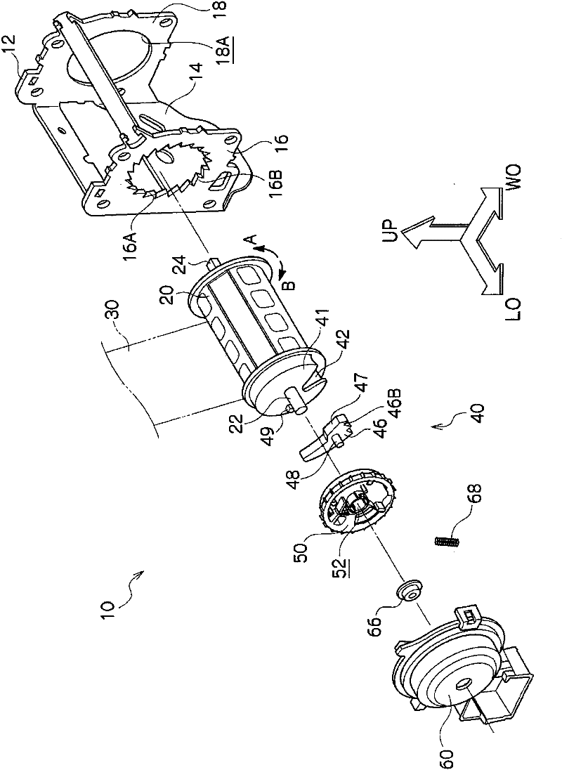
[0022] figure 2 The overall configuration of the seat belt take-up device 10 according to the embodiment of the present invention is shown in an exploded perspective view. In addition, in the figure, one side in the vehicle front-rear direction is indicated by an arrow LO, the vehicle width direction is indicated by an arrow WO, and the vehicle upper direction is indicated by an arrow UP.

[0023] Such as figure 2 As shown, the belt retractor 10 has a frame 12 . The frame 12 is composed of a roughly plate-shaped backboard 14 and a footboard 16 and a footboard 18 extending integrally from both ends of the backboard 14 in the width direction. The vehicle body, so that the seat belt take-up device 10 is installed on the vehicle body. A circular disposition opening 16A and a disposition opening 18A are respectively penetrating through the leg plate 16 and the leg plate 18 , and ratchet teeth 16B (internal teeth) are formed on the outer periphery of the disposition opening 16A...


PUM


Abstract

In a webbing take-up device, a housing chamber is provided integrally at an axial-direction end portion of the spool, and opens to an outer-side in a radial-direction of the spool. A lock plate is housed in the housing chamber, and a side surface of the housing chamber is engaged with the lock plate at a predetermined occasion, and rotation of the spool in a drawing-out direction is regulated. An opening-side end portion of the side surface is arranged at a position away from a slit in a circumferential-direction of the spool. Thus, a wall part passing the side surface and being along the axial-direction becomes larger, so strength of the spool can be enhanced. Further, an outer-side of the housing chamber in the axial-direction is closed, so strength of the housing chamber can be enhanced, with the result that the strength of the spool can be further enhanced.

Description

technical field [0001] The present invention relates to a seat belt winding device for winding a seat belt fastened to a vehicle occupant. Background technique [0002] In the seat belt winding device described in the following Patent Document 1, when the reel is suddenly rotated in the drawing direction, the lock plate provided in the moving groove in the reel engages with the ratchet teeth of the frame. Rotation of the spool in the extraction direction is thereby restricted. [0003] In addition, when the locking piece meshes with the ratchet teeth of the frame, one side surface of the movement groove of the reel engages with the locking piece, and a load is received from the locking piece. Therefore, the reel should have sufficient strength on one side of the moving slot. [0004] Here, a slit through which the base end portion of the seat belt is inserted is provided on the spool. Therefore, if one side of the circumferential moving groove of the reel is away from the...

Claims


Application Information

Patent Timeline
Patent Type & Authority Applications(China)
IPC IPC(8): B60R22/38
CPCB60R22/36B60R2022/3419B60R22/34B60R22/40
Inventor 立间笃角屋敷晃
Owner KK TOKAI RIKA DENKI SEISAKUSHO
Why Eureka
Try Eureka