
Thrust bearing for a gyratory crusher and method of supporting a vertical shaft in such a crusher

A technology of gyratory crushers and thrust bearings, applied in the direction of rotating bearings, bearings, shafts and bearings, etc., can solve problems such as high cost, limited capacity of cone crushers, wear of horizontal support plates, etc., and achieve cost reduction and reduction Small power loss and reduced mechanical wear

Inactive Publication Date: 2011-11-23
SANDVIK INTPROP AB
View PDF9 Cites 8 Cited by
  • Summary
  • Abstract
  • Description
  • Claims
  • Application Information

AI Technical Summary

Problems solved by technology

[0005] A disadvantage of the above-mentioned crusher is that the horizontal support plates as its components are subject to considerable wear, which requires frequent replacement of the thrust bearings at high cost
In addition, the capacity of the cone crusher is limited because the support plate can only bear loads up to a certain level

Method used


Image

  • Thrust bearing for a gyratory crusher and method of supporting a vertical shaft in such a crusher
  • Thrust bearing for a gyratory crusher and method of supporting a vertical shaft in such a crusher
  • Thrust bearing for a gyratory crusher and method of supporting a vertical shaft in such a crusher

Examples


Embodiment Construction

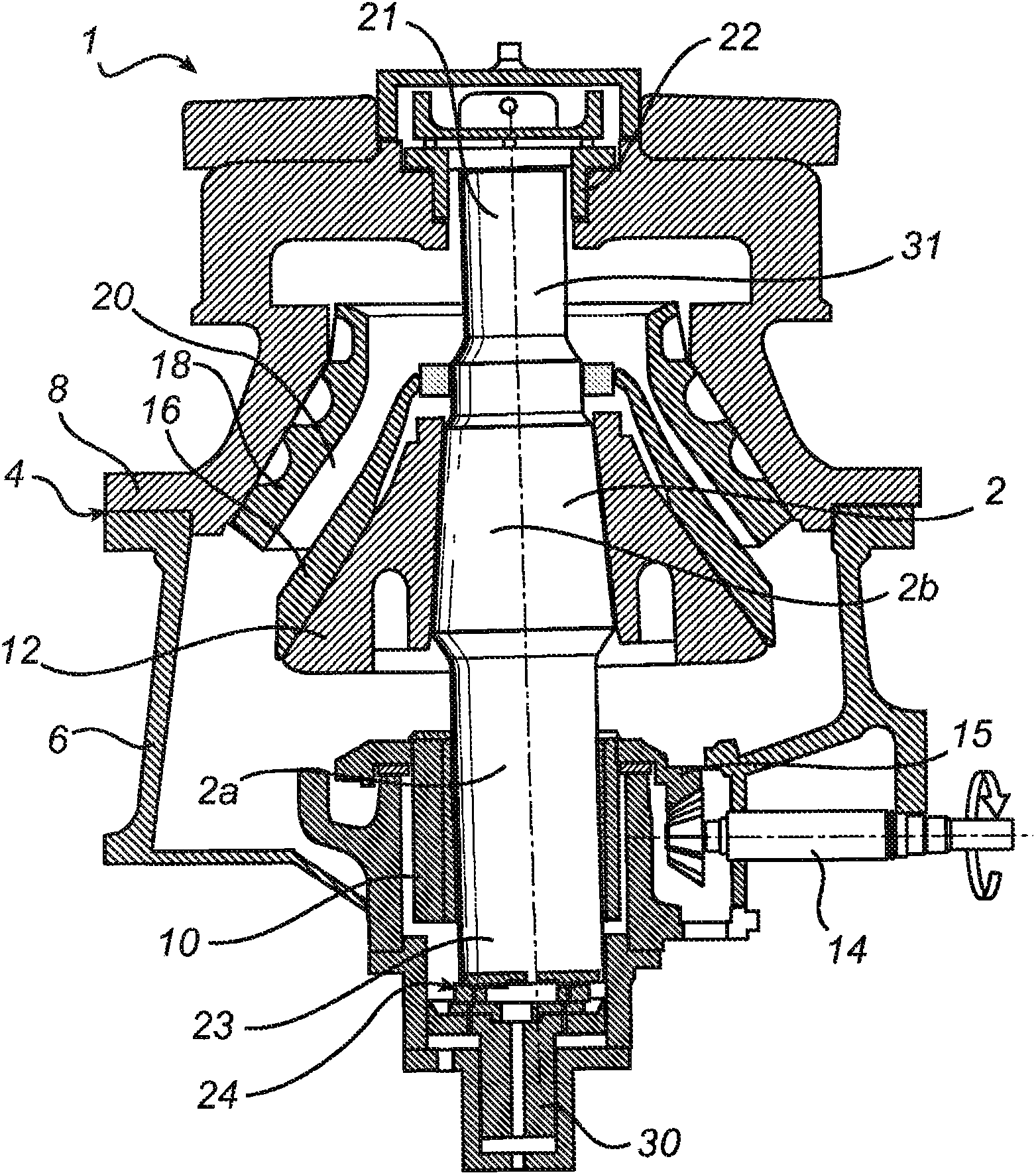
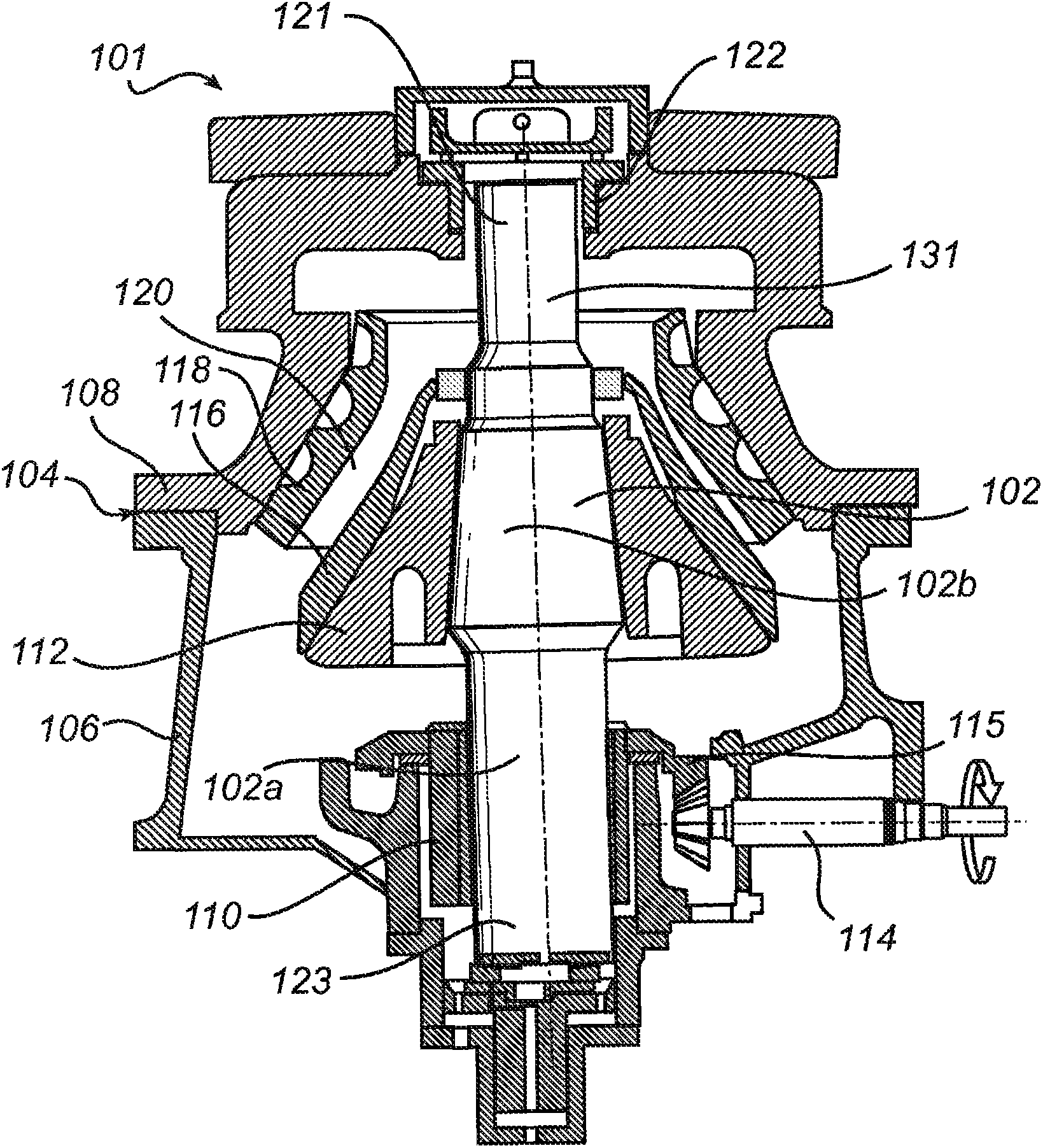
[0029] Figure 1a A gyratory crusher 1 according to a first embodiment is schematically shown. The gyratory crusher 1 has a vertical shaft 2 and a frame 4 comprising a frame bottom 6 and a frame top 8 . An eccentric in the form of an eccentric 10 is rotatably arranged around the lower part 2 a of the shaft 22 . The crushing head 12 is fixedly mounted on the upper part 2b of the shaft 2 . A drive shaft 14 is arranged to rotate the eccentric 10 via a motor (not shown) and a ring gear 15 mounted on the eccentric 10 . The vertical shaft 2 is supported at its upper end 21 in an upper cover bearing 22 in the frame top 8 . When the shaft 14 is driven to rotate the eccentric 10 during operation of the crusher 1, the shaft 2 and the crushing head 12 mounted thereon will perform a swivel movement.

[0030] The first crushing shell 16 is fixedly mounted on the crushing head 12 . The second crushing shell 18 is fixedly mounted on the frame top 8 . A crushing gap 20 is formed between ...


PUM


Abstract

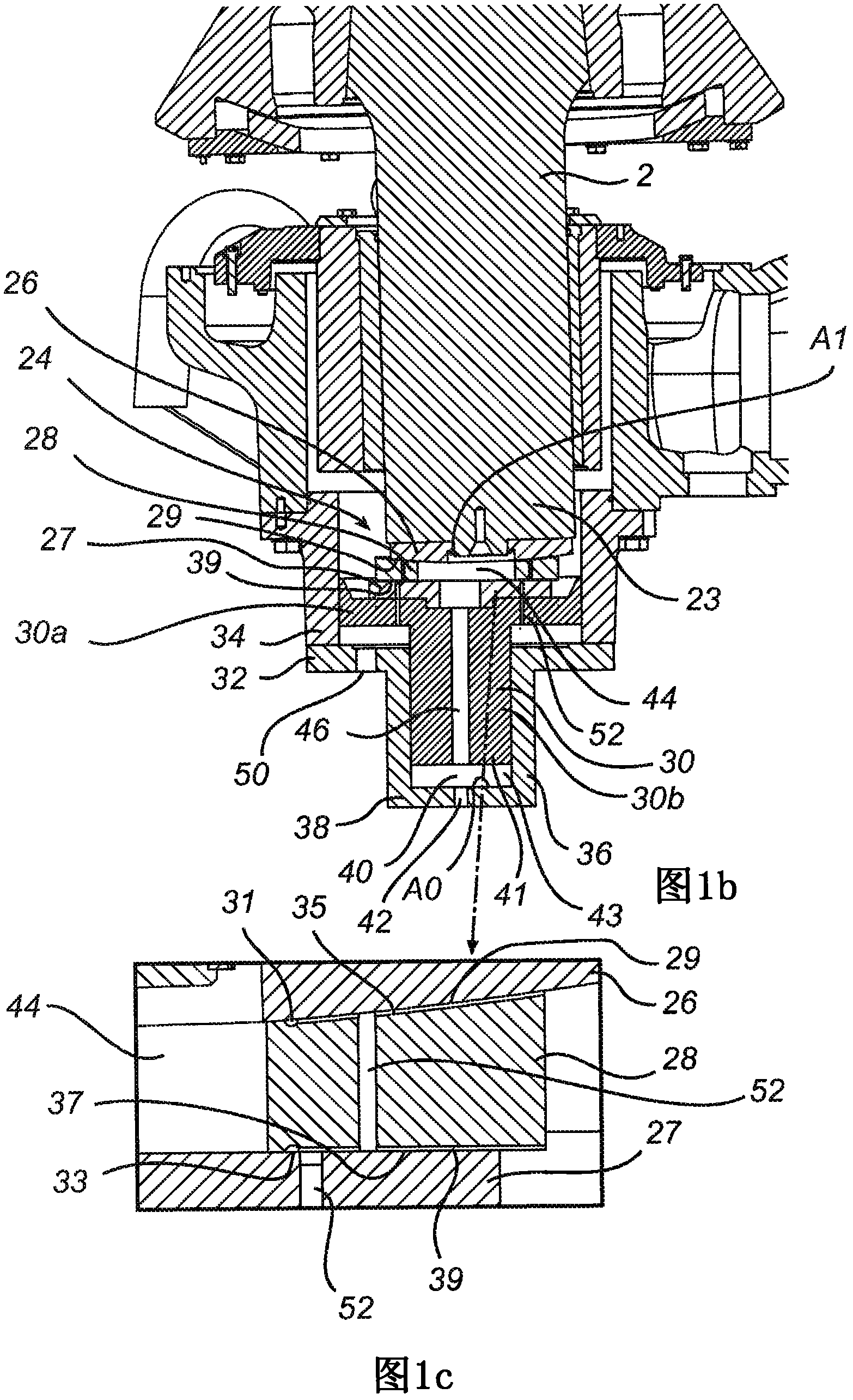
A gyratory crusher comprises a crushing head on which a first crushing shell is mounted, and a frame on which a second crushing shell is mounted. The crusher has a trust bearing (24) which is made up of horizontal bearing plates (26, 27, 28) and which is located between a vertical shaft (2) and a pis-ton (30) arranged vertically below the same. The crusher further has a first space (40), which is adapted to receive a variable amount of pressurized liquid, which first space (40) is defined by the piston (30) and a piston housing (32) formed in the frame, and a second space (44) which is adapted to receive, by way of a duct (46), pressurized liquid from the first space (40), which second space (44) is located between the vertical shaft (2) and the piston (30) and at least partly accommodated in an opening in at least one of said bearing plates (26, 27, 28). The first space (40) and the second space (44) are adapted by means of the liquid to transmit forces from the crushing head to the piston housing (32), in order that the load on the trust bearing (24) is relieved.

Description

technical field [0001] The invention relates to a gyratory crusher comprising a crushing head fixedly attached to the upper part of a generally vertical shaft and a frame, with a first crushing shell mounted on the crushing head and a second crushing shell Mounted on the frame, the second crushing shell defines a crushing gap together with the first crushing shell, the vertical position of the first crushing shell relative to the vertical position of the second crushing shell can be changed by using at least one adjustment device Position to adjust the width of the crushing gap, the above-mentioned gyratory crusher also includes a thrust bearing, the thrust bearing is composed of a horizontal support plate and is located between the vertical shaft and the piston vertically arranged below the vertical shaft, and the Thrust bearings are adapted to transmit the forces from the crushing head to the frame. [0002] The invention also relates to a method of supporting a substantial...

Claims


Application Information

Patent Timeline
Patent Type & Authority Applications(China)
IPC IPC(8): B02C2/04
CPCB02C2/047F16C17/18F16C23/048F16C32/067F16C32/0692F16C37/002
Inventor 帕特里克·舍贝里塞巴斯蒂安·佩尔松
Owner SANDVIK INTPROP AB
Learn More