Solar cell module
A technology of solar cells and electrical connectors, applied in photovoltaic modules, circuits, photovoltaic power generation, etc., can solve the problems of affecting photoelectric conversion efficiency, low photoelectric conversion efficiency, affecting the amount of sunlight penetrating the tube, etc., to achieve photoelectricity Effects of conversion efficiency improvement, material cost control, and cost increase
- Summary
- Abstract
- Description
- Claims
- Application Information
AI Technical Summary
Problems solved by technology
Method used
Image
Examples
no. 1 example
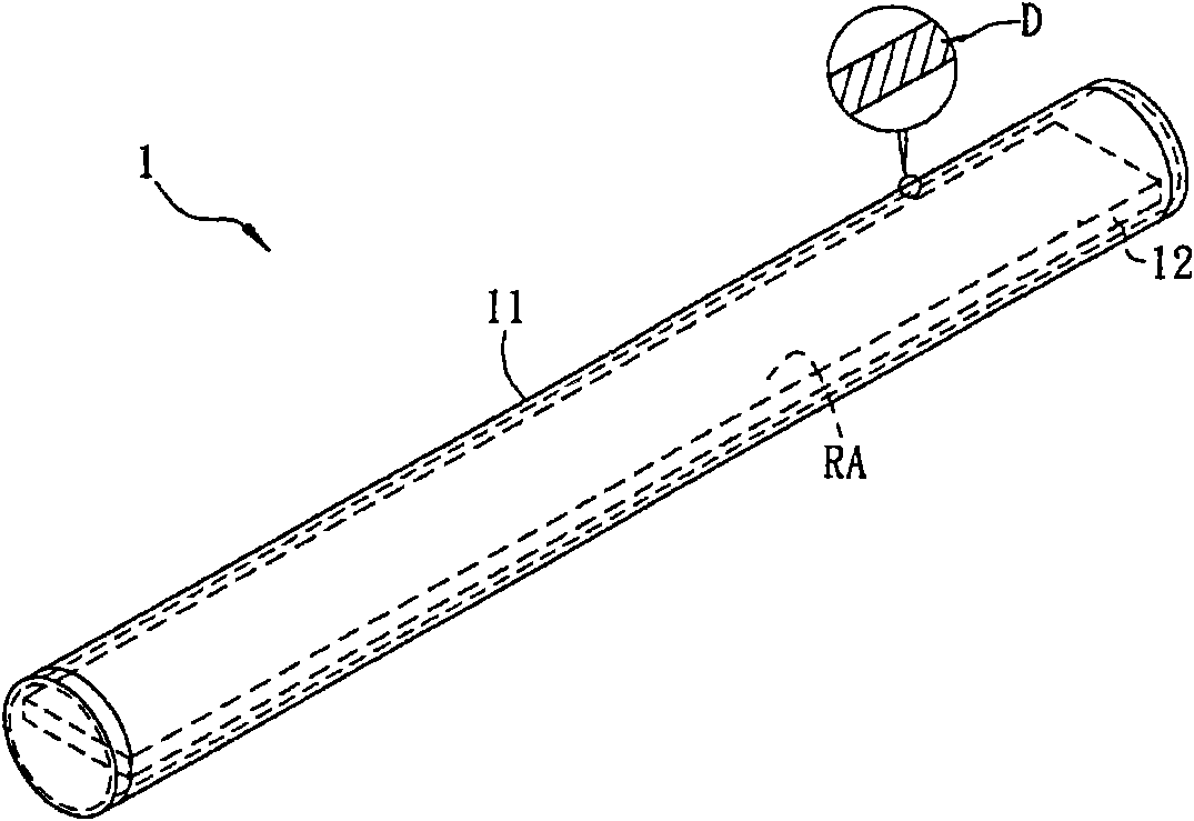
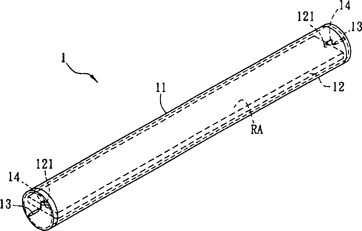
[0038] Please refer to figure 1 As shown, a solar cell module 1 according to the first embodiment of the present invention includes a tube body 11 and a solar cell assembly 12 .
[0039] The tube body 11 is at least partly transparent, and its transparent material can be, for example, glass, quartz or plastic, wherein the glass can be strengthened glass. Here, the strengthened glass can be formed by chemical strengthening treatment, and the inner wall and / or outer wall of the pipe body 11 can be strengthened to form a compressive stress layer. The compressive stress of the compressive stress layer can be above 100 MPa, and the compressive stress layer can be The thickness is more than 1 micron. The material of the tube body 11 may include SiO 2 、Al 2 o 3 , B 2 o 3 , Li 2 O, Na 2 O, K 2 O, MgO, CaO, ZnO, or ZrO 2 Wait. In this embodiment, the tube body 11 is taken as an example of a whole transparent tube body, of course, only the light-incident side of the tube body...
no. 2 example
[0051] Figure 5A and Figure 5B They are respectively a three-dimensional schematic diagram and a side view of a solar cell module 2 according to the second embodiment of the present invention. The solar cell module 2 includes a tube body 21 , a solar cell component 22 and two electrical connectors 23 . Wherein, the iron content weight ratio of the pipe body 21 is 700 ppm or less.
[0052] The main difference from the first embodiment is that the solar cell module 2 further includes a support component 25 disposed inside the tube body 21 , and the solar cell component 22 is disposed on the support component 25 . In this embodiment, the side edge of the support component 25 can contact and abut against the inner wall of the tube body 21 , so that the support component 25 is fixed on the tube body 21 . In this embodiment, one solar cell module 22 is set on the supporting component 25 as an example, of course, multiple solar cell components 22 can also be set on the supportin...
no. 3 example
[0064] Figure 9 It is an application schematic diagram of a solar cell module 3 according to the third embodiment of the present invention. A plurality of solar cell modules 3 are arranged side by side at intervals, and each solar cell module 3 includes a tube body 31 , a solar cell component 32 , two electrical connectors 33 and a supporting component 35 . Wherein, the electrical connector 33 is electrically connected to the two electrodes 321 of the solar cell module 32 through two wires 34 . Since the solar cell module 3 can apply the technical features of the solar cell modules in all the above-mentioned embodiments, it will not be repeated here.
[0065] There are plants planted under the solar cell module 3 , the solar cell module 3 of this embodiment can not only absorb light to generate electricity, but also provide plant cultivation through the light between the solar cell modules 3 , which makes the present invention very industrially applicable.
[0066] In addit...
PUM
 Abstract
Description
Claims
Application Information
 - R&D
- Intellectual Property
- Life Sciences
- Materials
- Tech Scout
- Unparalleled Data Quality
- Higher Quality Content
- 60% Fewer Hallucinations
Browse by: Latest US Patents, China's latest patents, Technical Efficacy Thesaurus, Application Domain, Technology Topic, Popular Technical Reports.
© 2025 PatSnap. All rights reserved.Legal|Privacy policy|Modern Slavery Act Transparency Statement|Sitemap|About US| Contact US: help@patsnap.com


