
Device and method for generating multi-channel sine wave phase standard signals

A standard signal and generating device technology, applied in the field of electronics, can solve the problems of fixed magnitude, reduced phase difference magnitude accuracy, difficulty in achieving accuracy, etc., and achieves the effect of high resolution

Active Publication Date: 2011-11-23
BEIJING CHANGCHENG INST OF METROLOGY & MEASUREMENT AVIATION IND CORP OF CHINA
View PDF4 Cites 13 Cited by
  • Summary
  • Abstract
  • Description
  • Claims
  • Application Information

AI Technical Summary

Problems solved by technology

In the past, the means of generating high-precision phase difference signals by controlling delay time, controlling trigger synchronization characteristics, and using passive delay networks have achieved good results, but they have been affected by amplitude factors such as circuit drift, noise, and waveform distortion, and Due to the influence of time factors such as circuit time base distortion, time base jitter, and synchronization delay error, it is difficult to achieve very high accuracy. In the case of output, higher accuracy can be obtained, but high-resolution phase adjustment fineness cannot be obtained, and the value is fixed and cannot be adjusted; 2) Using the principle of arbitrary wave generator to generate phase difference can have higher resolution and adjustment fineness , but it also needs to generate phase difference through delay and synchronization. The resolution is limited by the sampling interval. It only has high resolution at low frequency, and it is not easy to produce high resolution at high frequency; 3) single-point synchronization circuit is susceptible to level noise at the synchronization point , signal distortion, and level drift factors will reduce the accuracy of the phase difference value

Method used


Image

  • Device and method for generating multi-channel sine wave phase standard signals
  • Device and method for generating multi-channel sine wave phase standard signals
  • Device and method for generating multi-channel sine wave phase standard signals

Examples


Embodiment

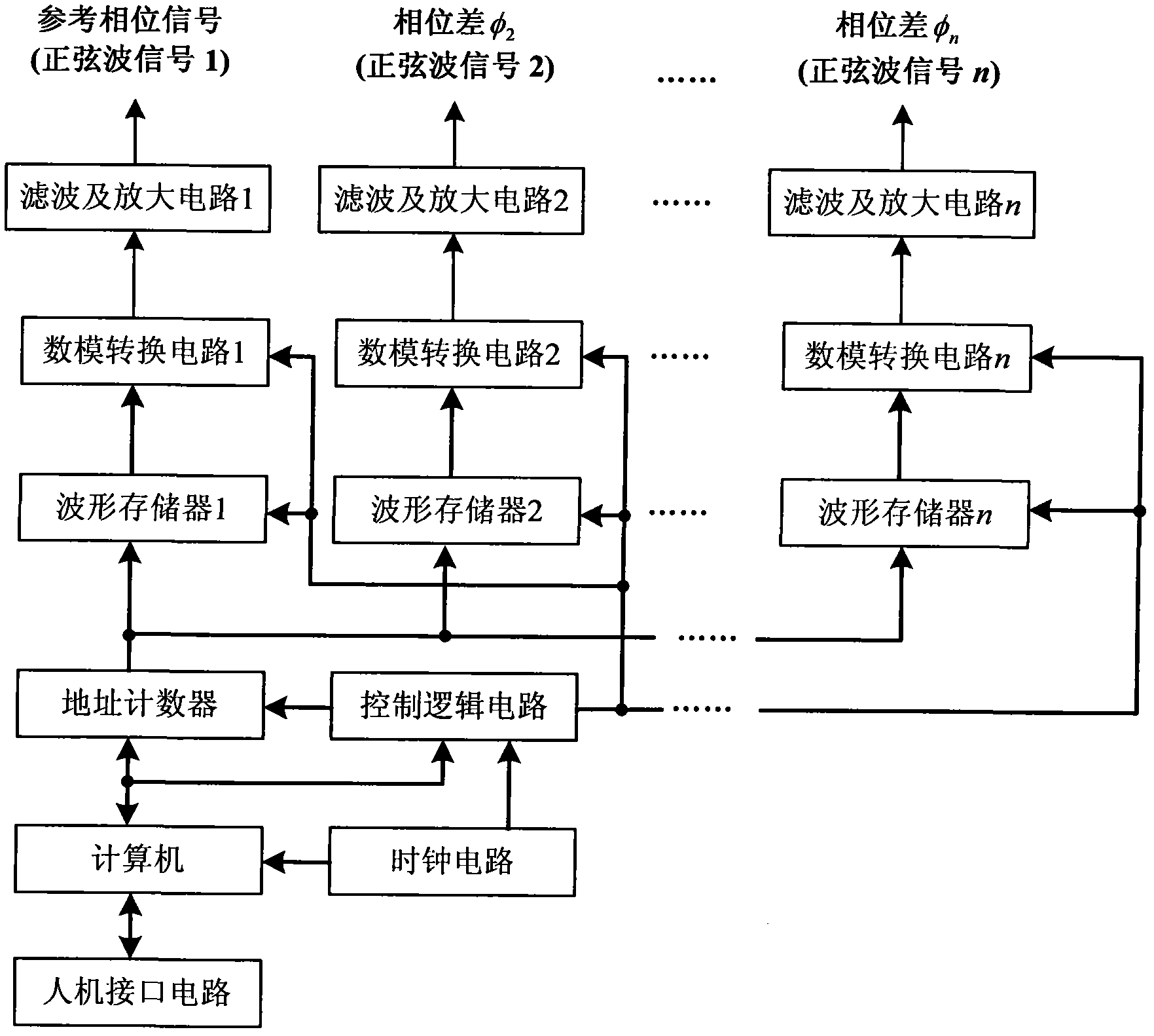
[0029] A multi-channel sine wave phase standard signal generating device, such as figure 1 As shown, it includes two or more filtering and amplifying circuits, two or more digital-to-analog conversion circuits, two or more waveform memories, and shared logic control circuits, address counters, computers, Human-machine interface circuit and clock circuit; among them, the number of filtering and amplifying circuits, digital-to-analog conversion circuits and waveform memory is the same, and they are used in one-to-one correspondence;

[0030] The clock circuit provides a unified clock signal for the logic control circuit and the computer. The computer provides common timing and logic control signals for each digital-to-analog conversion circuit, each waveform memory and address counter through the common control logic circuit. The computer communicates with the operator through the man-machine interface circuit. Realize human-computer interaction; the computer sends the single-pe...


PUM


Abstract

The invention relates to a device and a method for generating multi-channel sine wave phase standard signals and belongs to the technical field of electronics. The device comprises two or more filter and amplification circuits, two or more digital-to-analog conversion circuits, two or more waveform memories, a logic control circuit, an address counter, a computer, a human-machine interface circuit and a clock circuit, wherein the number of filter and amplification circuits, the number of digital-to-analog conversion circuits and the number of waveform memories are the same; and the filter andamplification circuits, the digital-to-analog conversion circuits and the waveform memories are correspondingly matched with one another one by one. The device is stable and reliable and high in resolution and is not influenced by factors such as noise, distortion and the like, and can generate multi-channel sine wave phase standard signals with adjustable phase differences among channels, and drifting is avoided; the common address counter and the control logic circuit avoid influences of factors such as time base distortion, time base dithering, synchronous time delay error and the like on the phase difference; and the device has the characteristic that phase difference values can be reproduced at high precision.

Description

technical field [0001] The invention relates to a device and a method for generating a multi-channel sine wave phase standard signal, in particular to a device and a method capable of generating a multi-channel sine wave phase standard with an arbitrarily adjustable phase difference between channels, and belongs to the technical field of electronics. Background technique [0002] Phase difference measurement and reproduction technology is one of the basic technologies in the field of electronic metrology, which is of great significance and far-reaching influence. For example, the power factor in AC electric energy metering test needs to measure the phase difference between two-phase or three-phase AC voltage and between voltage and current to be finally determined, and the time difference measurement in many occasions is obtained indirectly through phase difference measurement, so The determination and reproduction of phase standards has always been a basic problem in this f...

Claims


Application Information

Patent Timeline
IPC IPC(8): G01R1/28
Inventor 梁志国朱振宇张大鹏武腾飞李华丰
Owner BEIJING CHANGCHENG INST OF METROLOGY & MEASUREMENT AVIATION IND CORP OF CHINA
Learn More