
Loading device for high formwork support system full-scale test

A support system and tall formwork technology, applied in the direction of measuring devices, testing of machines/structural components, using stable tension/compression to test the strength of materials, etc., can solve the problems of low construction cost, high construction cost, uneven loading, etc. , to achieve the effect of low cost and simple structure

Inactive Publication Date: 2011-11-23
XI'AN UNIVERSITY OF ARCHITECTURE AND TECHNOLOGY
View PDF4 Cites 10 Cited by
  • Summary
  • Abstract
  • Description
  • Claims
  • Application Information

AI Technical Summary

Problems solved by technology

[0004] In order to overcome the shortcomings of the existing test device, such as large floor area, high construction cost and uneven loading, the purpose of the present invention is to provide a loading device for full-scale testing of tall formwork support systems. The test device not only has good loading effect, Small size and low construction cost

Method used


Image

  • Loading device for high formwork support system full-scale test
  • Loading device for high formwork support system full-scale test
  • Loading device for high formwork support system full-scale test

Examples


Embodiment Construction

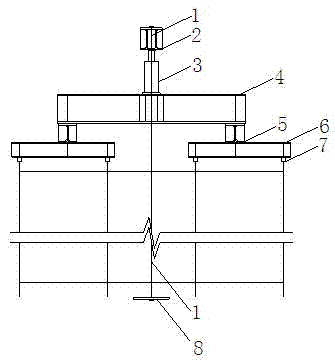
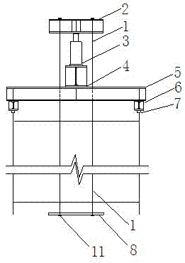
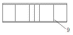
[0019] Refer to Fig. 1. Fig. 1 shows a schematic diagram of a loading device for a full-scale test of a tall formwork support system, including a force-transmitting steel bar 1, a reaction beam 2, a jack 3, a third-level distribution beam 4, a second-level distribution beam 5, a Grade distribution beam 6. The structure of the reaction beam 2 is shown in FIG. 2 , and the structure of the three-stage distribution beam 4 is shown in FIG. 3 .

[0020] The centers of the reaction beam 2, the jack 3, and the three-stage distribution beam 4 are on the same vertical line to ensure that the inaccuracy will not be caused by eccentricity during the loading process. From top to bottom, they are the reaction beam 2, jack 3, The third-level distribution beam 4, the second-level distribution beam 5, and the first-level distribution beam 6, wherein, the length direction of the second-level distribution beam 5 is perpendicular to the length direction of the third-level distribution beam 4, and...


PUM

PropertyMeasurementUnit
diameteraaaaaaaaaa
diameteraaaaaaaaaa

Abstract

The invention discloses a loading device for a high formwork support system full-scale test. The device mainly comprises a force transmission rebar, a counterforce beam, a jack, a tertiary distributive girder, secondary distributive girders and first distributive girders. An upper end of the force transmission rebar is connected with the counterforce beam, and a lower end of the transmission rebar is connected with a connection board through bolts fixed in a ground groove; the jack is arranged under the counterforce beam, and the tertiary distributive girder is arranged under the jack; two ends of the tertiary distributive girder are equipped with the secondary distributive girders, wherein a length direction of the tertiary distributive girder is perpendicular to length directions of thesecondary distributive girders. Similarly, two ends of each secondary distributive girder are equipped with the first distributive girders, wherein length directions of the secondary distributive girders are perpendicular to length directions of the first distributive girders; each top of test vertical rods is disposed inside a sleeve, and each vertical rod is applied with load through the first distributive girders. The loading device of the present invention can load accurately and easily control loading steps and loads, and is convenient for step-by-step loading in the high formwork support system full-scale test.

Description

technical field [0001] The invention belongs to the field of design and research of a tall formwork support system, relates to a loading device for a full-scale test of a tall formwork support system, and is particularly suitable for loading in a compression test of a tall formwork support system. Background technique [0002] At present, when designing and researching the support system of tall formwork, the loading device of the bearing capacity test basically consists of three parts: the reaction frame, the jack, and the distribution beam. The loading of the jack is used to simulate the load during the construction period. The general reaction frame is provided by the installation of the laboratory. However, due to the large volume and floor space of the reaction frame, the installation cost is high, so there are few laboratories at present, so it is common It is not easy to realize the loading of the tall formwork support system. [0003] In addition, the general loadin...

Claims


Application Information

Patent Timeline
Patent Type & Authority Applications(China)
IPC IPC(8): G01N3/12G01N3/02G01M99/00
Inventor 胡长明范小周梅源车佳玲宋方方程佳佳汪杰
Owner XI'AN UNIVERSITY OF ARCHITECTURE AND TECHNOLOGY
Learn More