
Valve rod

A technology of valve stem and rotating rod, which is applied in the direction of lifting valve, valve device, engine components, etc., and can solve the problem of sealing plug or sealing port wear, sealing plug head circular runout, difficulty in ensuring coaxiality, and difficulty in matching and sealing, etc. problems, to achieve the requirements of reducing hardness, improving service life, and eliminating shape and position errors

Active Publication Date: 2011-11-23
朱成伟
View PDF5 Cites 2 Cited by
  • Summary
  • Abstract
  • Description
  • Claims
  • Application Information

AI Technical Summary

Problems solved by technology

[0003] Current stems such as Figure 4 As shown, the valve stem includes a rotating rod and a sealing plug. The rotating rod and the sealing plug are integrally structured. The valve stem mainly has the following disadvantages: 1) Due to the influence of processing technology and processing equipment, the sealing plug It is difficult to guarantee the circular runout and coaxiality, and the sealing effect is not good, so that the after-sales maintenance of the product is very large, resulting in a great waste of manpower and financial resources; 2) In the process of use, the sealing plug and the sealing port (valve hole) ) for circular friction, because the user over-tightens the valve stem in order to achieve a better sealing effect, it is very easy to cause severe wear of the sealing plug or sealing port (valve hole), resulting in difficult sealing and the product being scrapped; 3) The hardness of the valve hole material varies with the quality of the material, making it more difficult for the valve stem to seal with these materials as the hardness of the material decreases. The valve stem limits the application and development of low hardness materials

Method used


Image

  • Valve rod
  • Valve rod
  • Valve rod

Examples


Embodiment 2

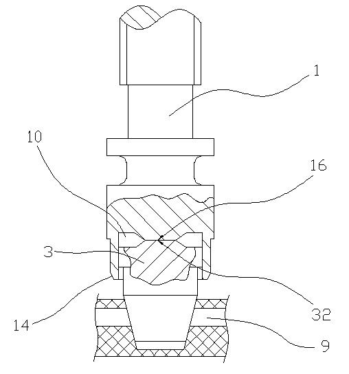
[0024] Embodiment 2. Compared with Embodiment 1, the only difference is that the top wall of the first concave hole 10 is in direct contact with the upper end surface of the sealing plug 3 . The upper end surface of the sealing plug 3 is a narrowing surface 32, so that when the top wall of the first concave hole 10 is in contact with the upper end surface of the sealing plug 3, the friction force is small, so that when the rotating rod 1 rotates, the sealing Plug 3 does not rotate together. It can be understood that a narrowing surface 16 can also be provided on the top wall of the first concave hole 10, as long as the top wall of the first concave hole 10 is in contact with the upper end surface of the sealing plug 3, the frictional force is small. Can.


PUM


Abstract

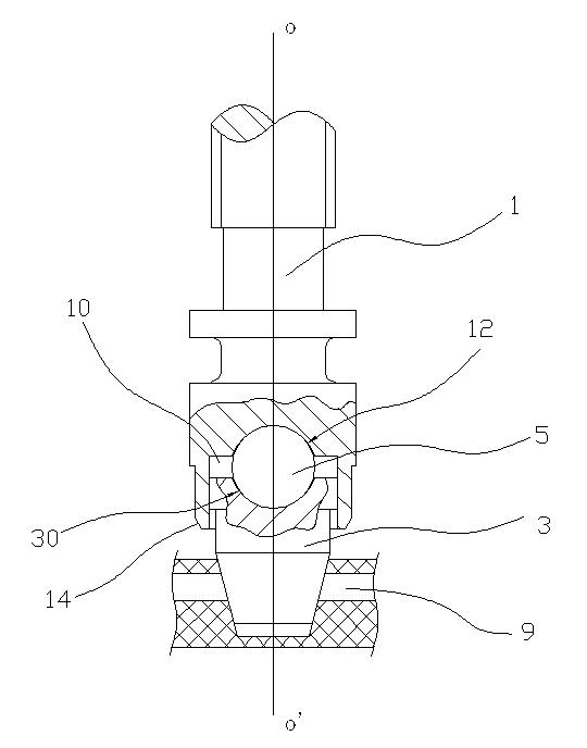
The invention discloses a valve rod comprising a rotary rod and a sealing plug. The valve rod is characterized in that the rotary rod and the sealing plug are of a split structure, and the rotary rod and the sealing plug can relatively rotate; and an end face pressing down the sealing plug is at least arranged on the rotary rod. In the valve rod disclosed by the invention, the rotary rod rotates and does not drive the sealing plug to rotate, and the sealing plug is pressed down when the rotary rod is screwed down so that the sealing plug only moves up and down, but not moves circularly, thus the abrasion of a conical surface or a sealing opening (a valve hole) of the sealing plug is reduced and the service life of the sealing plug is largely prolonged.

Description

technical field [0001] The invention relates to a valve stem, which can be applied to cutting tools, flow meters and other products. Background technique [0002] Products such as cutting tools and flowmeters are provided with a valve stem, and the valve stem is mainly used to cooperate with the valve hole to realize sealing and throttling of the product and fine-tuning of the flow rate. [0003] Current stems such as Figure 4 As shown, the valve stem includes a rotating rod and a sealing plug. The rotating rod and the sealing plug are integrally structured. The valve stem mainly has the following disadvantages: 1) Due to the influence of processing technology and processing equipment, the sealing plug It is difficult to guarantee the circular runout and coaxiality, and the sealing effect is not good, so that the after-sales maintenance of the product is very large, resulting in a great waste of manpower and financial resources; 2) In the process of use, the sealing plug an...

Claims


Application Information

Patent Timeline
Patent Type & Authority Applications(China)
IPC IPC(8): F16K1/00F16K1/48F16K1/32
Inventor 朱成伟罗光华
Owner 朱成伟
Learn More