
Medium accumulation conveyance device

A medium conveying and medium technology, which is applied in the field of medium accumulating and sending out devices, can solve the problems of shortening the life of the device, increasing the cost, complicated structure, etc., and achieving the effect of prolonging the life and saving space.

Inactive Publication Date: 2011-11-23
DIGITAL CHINA JINXIN TECH
View PDF5 Cites 13 Cited by
  • Summary
  • Abstract
  • Description
  • Claims
  • Application Information

AI Technical Summary

Problems solved by technology

[0013] However, the above-mentioned conventional medium storage and delivery device has the following problems: it requires an escape space for avoiding the impeller 5 during delivery, which leads to an increase in the size of the device and a complicated structure, resulting in an increase in cost.
[0016] However, in the medium storage and delivery device of the above-mentioned prior art document, although space saving and low cost are achieved, the blades are always in contact with the impeller cover during storage and delivery, so there is a problem that the impeller is easy to wear and the device has a long life. shortened question

Method used


Image

  • Medium accumulation conveyance device
  • Medium accumulation conveyance device
  • Medium accumulation conveyance device

Examples


Embodiment 1

[0028] (structure)

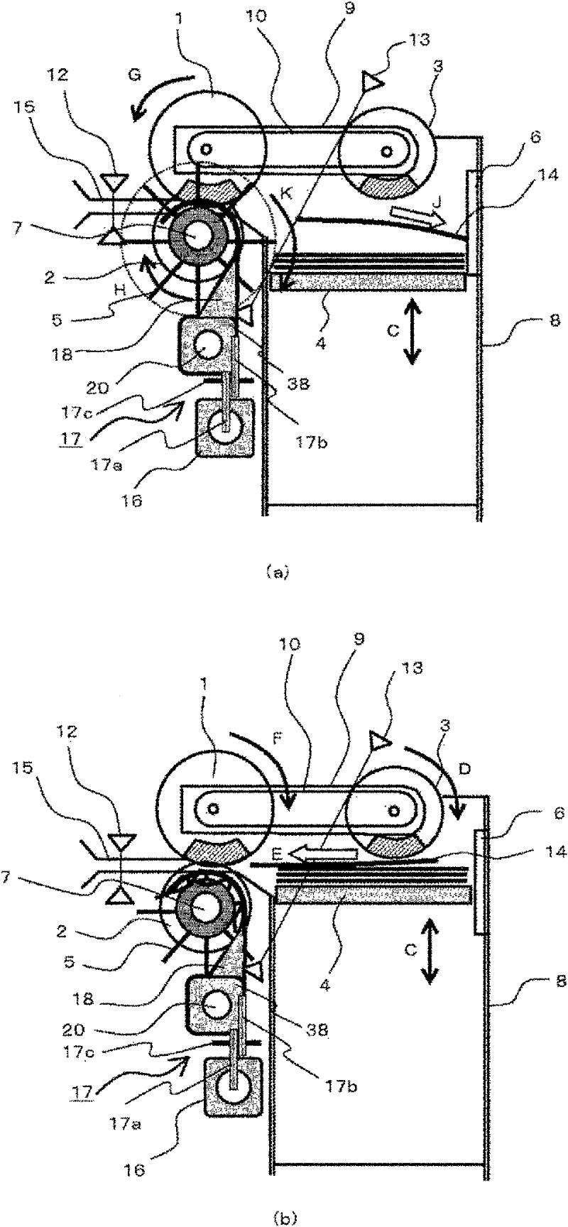
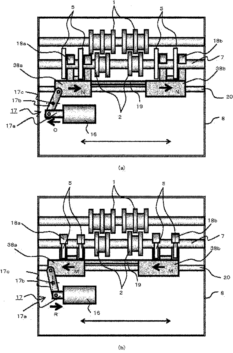
[0029] figure 1 It is a side view showing the main part structure of the medium storage and delivery device of the first embodiment, figure 2 represents its front view, figure 1 (a) and figure 2 (a) shows the state at the time of banknote accumulation, figure 1 (b) and figure 2 (b) shows the state when a banknote is sent out.

[0030] In addition, feed roller 1, back roller 2, pick-up roller 3, stage 4, impeller 5, banknote retainer 6, rotating shaft 7, banknote storage section 8, pick-up arm 9, drive belt 10, conveyance path 15, travel sensor 12 and the above sensor 13 with the use of Figure 5 The configuration of the conventional medium storage and delivery device described is basically the same, so a detailed description thereof will be omitted for simplification.

[0031] Such as figure 1 , figure 2 As shown, the medium storage and delivery device of Embodiment 1 is configured to expand the blades of the impeller 5 when banknotes are a...

Embodiment 2

[0048] (structure)

[0049] The structure of the medium storage and delivery device of the second embodiment is the same as that of the first embodiment except for the mechanism for moving the impeller cover, so detailed description of the same structure will be omitted for the sake of simplification.

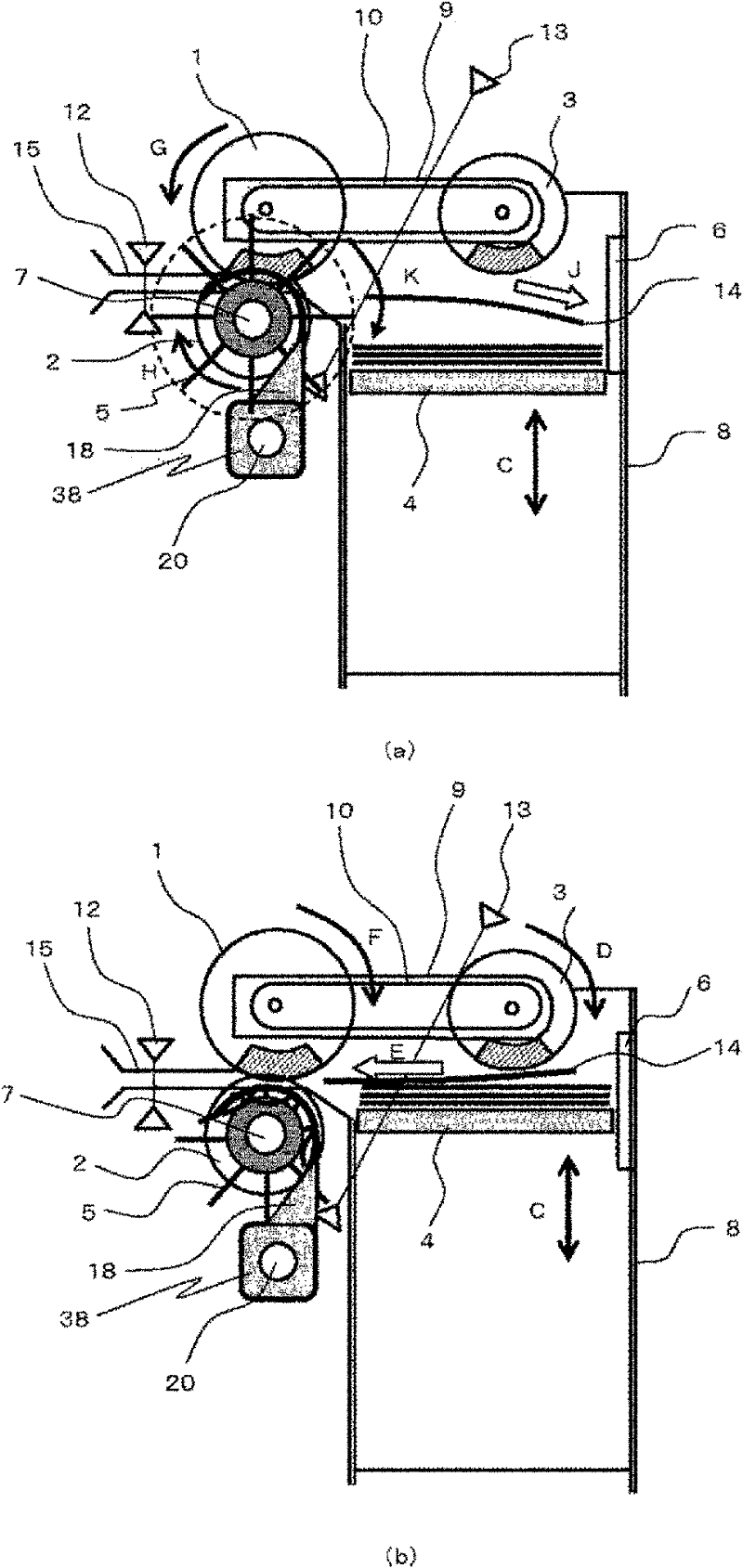
[0050] image 3 It is a side view showing the main part structure of the medium storage and delivery device of the second embodiment, Figure 4 represents its front view, image 3 (a) and Figure 4 (a) shows the state at the time of banknote accumulation, image 3 (b) and Figure 4 (b) shows the state when a banknote is sent out.

[0051] As shown in the figure, in the medium storage and delivery device of Embodiment 2, threaded holes are provided on the cover sliders 38a, 38b on which the impeller covers 18a, 18b are mounted, and the cover sliders 38a, 38b are provided on the slide shaft 20. The threaded shape 22 in which the threaded hole of 38b is screwed is provided a...


PUM


Abstract

The invention discloses a medium accumulation conveyance device, wherein an impeller (5) can be avoided via a space-saving structure so as to prolong the service life of the impeller (5). The medium accumulation conveyance device flaps bank notes (14) via a rotating impeller (5) for the accumulation and sends out the accumulated bank notes (14). The impeller (5) comprises a plurality of flexible blades. The medium accumulation conveyance device comprises a cover slip holder (38) and an impeller cover (18) capable of moving in a direction vertical to the medium conveying direction is arranged on the cover slip holder (38). When the medium is accumulated, the cover slip holder (38) is moved, so that the impeller cover (18) deviates from the position of the impeller (5). When the medium is sent out, the cover slip holder (38) is also moved, so that the impeller cover (18) covers the impeller (5).

Description

technical field [0001] The present invention relates to a medium storage and delivery device that uses an impeller to store a sheet-like medium and sends out the stored medium. Background technique [0002] Generally, in an automatic teller machine or the like that handles paper sheets such as banknotes as a medium, the paper sheets deposited by a deposit transaction can be stored in a banknote storage for each currency type, and the paper sheets can be deposited by a withdrawal transaction. Pages are sent out from the banknote storage and banknotes are ejected. [0003] Figure 5 It is a side view showing the structure of a conventional medium storage and delivery device that performs storage and delivery of the paper sheets, Figure 5 (a) indicates the state at the time of delivery, Figure 5 (b) shows the state at the time of accumulation. [0004] In this figure, 14 is a banknote to be accumulated or sent out, 8 is a banknote storage unit, and 4 is a stage for storing b...

Claims


Application Information

Patent Timeline
IPC IPC(8): B65H29/40G07D11/00
CPCB65H2404/1114B65H2404/693
Inventor 细川和宏
Owner DIGITAL CHINA JINXIN TECH
Learn More