
Optical module and method for protecting optical layer

An optical module and optical fiber technology, applied in the field of optical module and optical layer protection, can solve the problems of high maintenance cost, high cost, large investment, etc., and achieve the effect of low optical layer protection and low cost

Inactive Publication Date: 2011-11-16
HUAWEI TECH CO LTD
View PDF3 Cites 6 Cited by
  • Summary
  • Abstract
  • Description
  • Claims
  • Application Information

AI Technical Summary

Problems solved by technology

[0004] In the process of realizing the present invention, the inventor found that: in the above-mentioned first solution, one more interface is added, and the interface is an important resource, which results in high cost and high cost; in the above-mentioned second solution, It is necessary to establish a transmission equipment network, such as SDH (Synchronous Digital Hierarchy, Synchronous Digital System) or WDM (Wavelength Division Multiplex, Wavelength Division Multiplexing), which requires large investment and high maintenance costs

Method used


Image

  • Optical module and method for protecting optical layer
  • Optical module and method for protecting optical layer
  • Optical module and method for protecting optical layer

Examples


Embodiment Construction

[0019] In order to make the purpose, technical solutions and advantages of the embodiments of the present invention clearer, the technical solutions in the embodiments of the present invention will be clearly and completely described below in conjunction with the drawings in the embodiments of the present invention. Obviously, the described embodiments It is a part of embodiments of the present invention, but not all embodiments. Based on the embodiments of the present invention, all other embodiments obtained by persons of ordinary skill in the art without making creative efforts belong to the protection scope of the present invention.

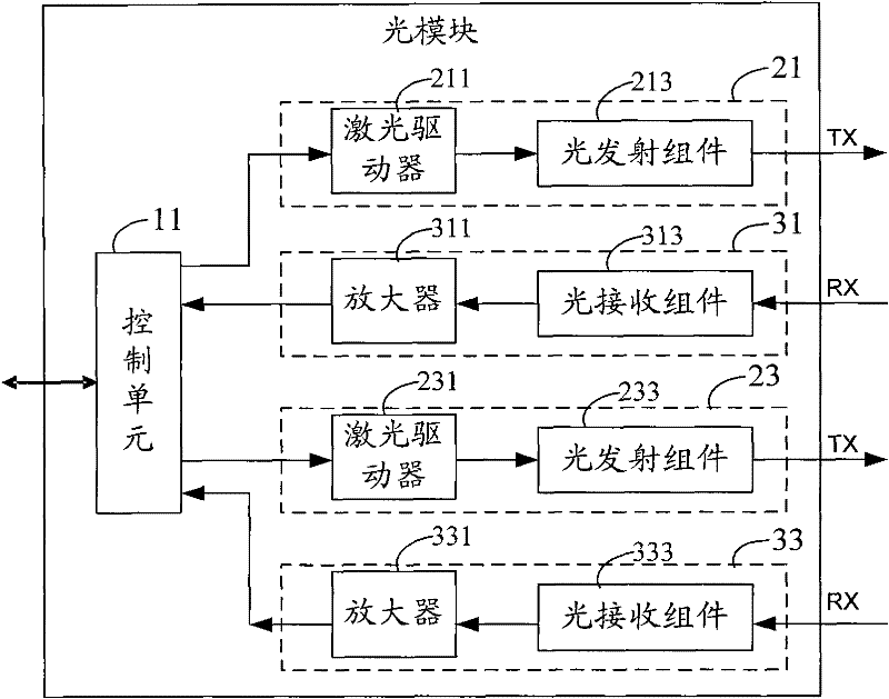
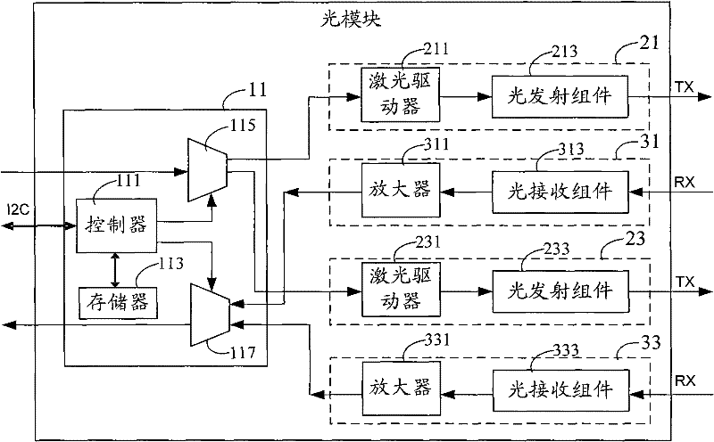
[0020] figure 1 It is a schematic structural diagram of Embodiment 1 of the optical module of the present invention, such as figure 1 As shown, the optical module includes: a control unit 11, at least two light emitting units (light emitting unit 21 and light emitting unit 23) and at least two light receiving units (light receiving unit 31 a...


PUM


Abstract

The embodiment of the invention provides an optical module and a method for protecting an optical layer. The optical module comprises a control unit, at least two light-emitting units and at least two optical receiving units, wherein the control unit is connected with an external CPU (central processing unit) and connected with the at least two light-emitting units and the at least two optical receiving units respectively; and the at least two light-emitting units and the at least two optical receiving units are connected with external optical fibers respectively. According to the embodiment of the invention, the at least two light-emitting units and the at least two optical receiving units are placed in the optical module so as to form a main transmitting channel and a standby transmitting channel as well as a main receiving channel and a standby receiving channel respectively, thus being capable of flexibly switching to the standby channels when the main channels fail, thereby realizing the flexible and low-cost protection of the optical layer.

Description

technical field [0001] The invention relates to the field of communication technology, in particular to an optical module and an optical layer protection method. Background technique [0002] The point-to-point optical interconnection of data equipment can be realized through transmission equipment or bare optical fiber. To ensure the reliability of data transmission, optical layer protection is required for optical lines. [0003] The existing optical layer protection schemes can include the following two types: First, in the scheme of realizing optical interconnection through bare optical fibers, since SFP / SFP+ / XFP optical modules are used for optical interconnection, one optical path corresponds to one optical module, and one optical The module corresponds to an interface, so one more interface and the optical module and optical path corresponding to the interface are added as backup links to realize optical layer protection; among them, SFP is a small form-factor plugga...

Claims


Application Information

Patent Timeline
Patent Type & Authority Applications(China)
IPC IPC(8): H04B10/08H04B10/04H04B10/06H04B10/12H04B10/032H04B10/25H04B10/50H04B10/60
Inventor 郭蓥
Owner HUAWEI TECH CO LTD
Learn More