
Method and device for dynamically regulating antenna calibration position

An antenna calibration and dynamic adjustment technology, applied in diversity/multi-antenna systems, wireless communication, space transmit diversity, etc., can solve the problems of antenna calibration and calibration accuracy decline, inability to calibrate, etc., to improve calibration accuracy, prevent frequent alarms, Resolving the effect of disturbed calibration

Active Publication Date: 2011-11-16
DATANG MOBILE COMM EQUIP CO LTD
View PDF3 Cites 16 Cited by
  • Summary
  • Abstract
  • Description
  • Claims
  • Application Information

AI Technical Summary

Problems solved by technology

In the existing antenna calibration technology, the fixed position of the antenna calibration time slot will be affected by the interference between the base stations, resulting in a decrease in the accuracy of the antenna calibration, especially the calibration of the receiver, or even impossible calibration, resulting in frequent calibration alarms

Method used


Image

  • Method and device for dynamically regulating antenna calibration position
  • Method and device for dynamically regulating antenna calibration position
  • Method and device for dynamically regulating antenna calibration position

Examples


Embodiment Construction

[0033] Embodiments of the present invention are described in detail below, examples of which are shown in the drawings, wherein the same or similar reference numerals designate the same or similar elements or elements having the same or similar functions throughout. The embodiments described below by referring to the figures are exemplary only for explaining the present invention and should not be construed as limiting the present invention.

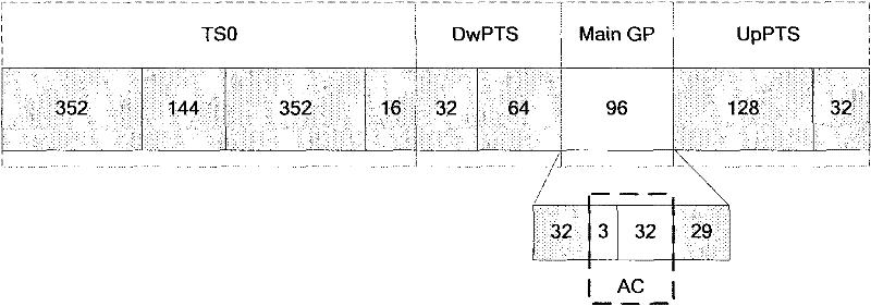
[0034] In order to better explain the present invention, the antenna calibration and the position of the antenna calibration time slot are firstly introduced. Specifically, when the antenna is transmitting for calibration, the calibration channel is in the receiving state, and the working channel is in the transmitting state. The working channel sends a calibration sequence at a fixed position in the time slot, and the calibration channel uses the received calibration sequence to calculate the phase and amplitude deviation of each channe...


PUM


Abstract

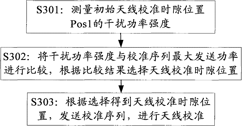
The embodiment of the invention provides a method for dynamically regulating an antenna calibration position, comprising the following steps: measuring the interference power intensity Pinter of an initial antenna calibration TS (time slot) position Pos1 in accordance with signals eac received by the initial antenna calibration TS position Pos1; comparing the interference power intensity Pinter with the maximum transmission power Pmax of calibration sequences, and selecting the antenna calibration TS position in accordance with the comparison result; and according to the selected antenna calibration TS position, transmitting the calibration sequences to carry out the antenna calibration. The embodiment of the invention also provides a device for dynamically regulating the antenna calibration position, comprising a measurement module, a selection module and a calibration module. The method and device provided by the invention can be used to improve the antenna calibration accuracy, prevent the frequent warning of the antenna calibration and solve the problem that the intelligent antenna calibration is interfered.

Description

technical field [0001] The present invention relates to the field of mobile communication, in particular, the present invention relates to a method and a device for dynamically adjusting an antenna calibration position. Background technique [0002] Mobile and broadband have become the development direction of modern communication technology. How to eliminate the influence of co-channel interference, multiple access interference and multipath fading has become the main factor that people consider when improving the performance of wireless mobile communication systems. In recent years, smart antenna technology has become a research hotspot in the field of mobile communication. [0003] Smart antenna technology brings great advantages to mobile communication systems. At present, the smart antenna technology has been regarded as one of the main development directions of the physical layer communication technology. Smart antenna technology can be used not only in TDD (Time Div...

Claims


Application Information

Patent Timeline
IPC IPC(8): H04B7/04H04W24/08
Inventor 徐红艳陈东康绍莉
Owner DATANG MOBILE COMM EQUIP CO LTD
Learn More