Reverse single-standby service continuity realization method and system
A continuity and business technology, applied in the communication field, to achieve the effect of ensuring business continuity
- Summary
- Abstract
- Description
- Claims
- Application Information
AI Technical Summary
Problems solved by technology
Method used
Image


Examples
Embodiment 1
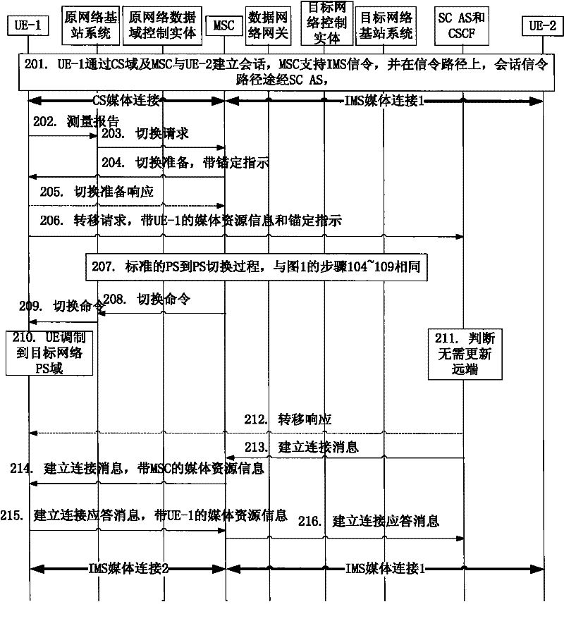
[0053] The handover preparation notification, the transfer request, and the connection establishment message all carry session association information;
[0054] In the connection establishment step, the connection establishment message forwarded by the current MSC to the terminal carries the media resource information of the current MSC;
[0055] The current MSC establishes a media connection with the terminal after receiving the message carrying media resource information from the terminal;
[0056] The current MSC associates the media connection between the current MSC and the terminal and the media connection between the current MSC and the remote end according to the session association information.
[0057] When the signaling is anchored to the current MSC, in order to ensure the successful establishment of the media connection: in the connection establishment step, the current MSC retries to forward the Establish connection message. See embodiment one, two.
[0058] W...
Embodiment 2
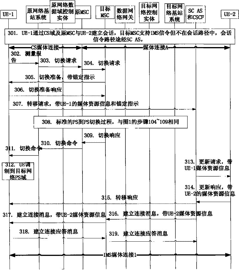
[0101] image 3 It is a flow chart of Embodiment 2 of the method for implementing reverse single-standby service continuity of the present invention, describing that a call is established between UE-1 and UE-2, and UE-1 establishes the call through the CS domain of the 2 / 3G network, Therefore, UE-1 is connected to a CS media connection in the call media path. When UE-1 moves and needs to change its access mode to LTE or HSPA PS domain, the subsequent session is anchored through the signaling of the target MSC but not the media When the media connection is anchored and the target MSC is not the original MSC, UE-1 and the SC AS interact through the MSC, and the process for UE-1 to realize reverse single-standby service continuity includes the following steps:
[0102] Step 301, UE-1 establishes a session with UE-1 through the CS domain and the original MSC, the target MSC supports IMS signaling but is not in the signaling path, and the session signaling path passes through the S...
Embodiment 3
[0127] Figure 4 It is a flow chart of Embodiment 3 of the method for implementing reverse single-standby service continuity of the present invention, describing that a call is established between UE-1 and UE-2, and UE-1 establishes a call through CS domain access, so the call media The path connecting UE-1 is a CS media connection. When UE-1 moves and needs to change its access mode to LTE or HSPA PS domain, the target MSC is not in the signaling path of subsequent sessions, and the target MSC is not the original In the case of MSC, UE-1 and SC AS interact directly, and the process of realizing reverse single-standby service continuity includes the following steps:
[0128] Steps 401-404, and image 3 301~304 are the same;
[0129] Step 405, MSC receives the handover request from the CS domain, and immediately sends a handover preparation message to UE-1, such as sending a request to UE-1 through a short message (SMS) or an unstructured supplementary service data service (U...
PUM
 Abstract
Description
Claims
Application Information
 - R&D
- Intellectual Property
- Life Sciences
- Materials
- Tech Scout
- Unparalleled Data Quality
- Higher Quality Content
- 60% Fewer Hallucinations
Browse by: Latest US Patents, China's latest patents, Technical Efficacy Thesaurus, Application Domain, Technology Topic, Popular Technical Reports.
© 2025 PatSnap. All rights reserved.Legal|Privacy policy|Modern Slavery Act Transparency Statement|Sitemap|About US| Contact US: help@patsnap.com