


Quick Research
Generate reliable direction feasibility study reports for your R&D in just a few steps.

Technical Q&A
Discover and master advanced knowledge NOW. Basics, ideas, possibilities, all at once.

Find Solutions
As an expert in R&D theories, this can generate solutions to your technical problems instantly.

Evaluate Feasibility
Analyze your overall solution with one click, know your potential R&D risks in advance.

Monitor Landscape
Get weekly tech updates, stay abreast of the latest tech innovations and key insights.
Cyclone drying and solvent recycling system
A recovery system and swirling flow technology, applied in the direction of drying solid materials, drying gas arrangement, drying, etc., can solve the problem of direct drying of unsuitable filter cake or agglomerated materials, so as to improve drying efficiency, large processing capacity, The effect of low dust removal pressure
- Summary
- Abstract
- Description
- Claims
- Application Information
AI Technical Summary
Problems solved by technology
Method used
Image

Examples
Embodiment 1
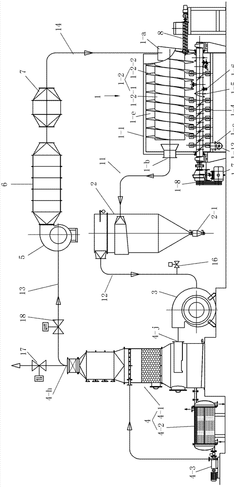
[0022] See Figure 1 to Figure 11 , This embodiment has a drying host 1, a bag dust removal device 2, an induced draft fan 3, a composite condensing device 4, a blower 5, a heater 6, and a filter 7.
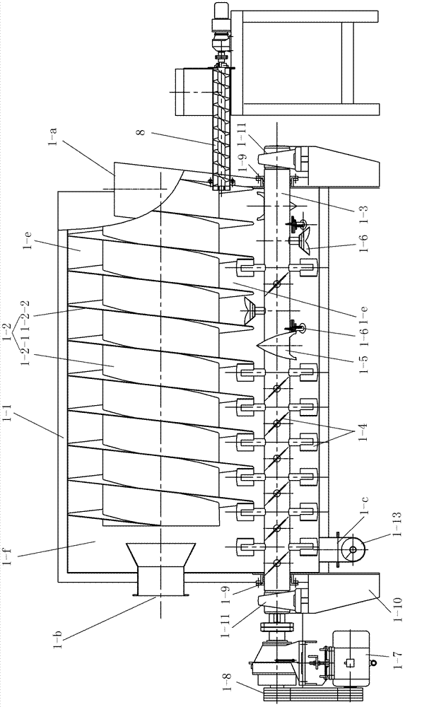
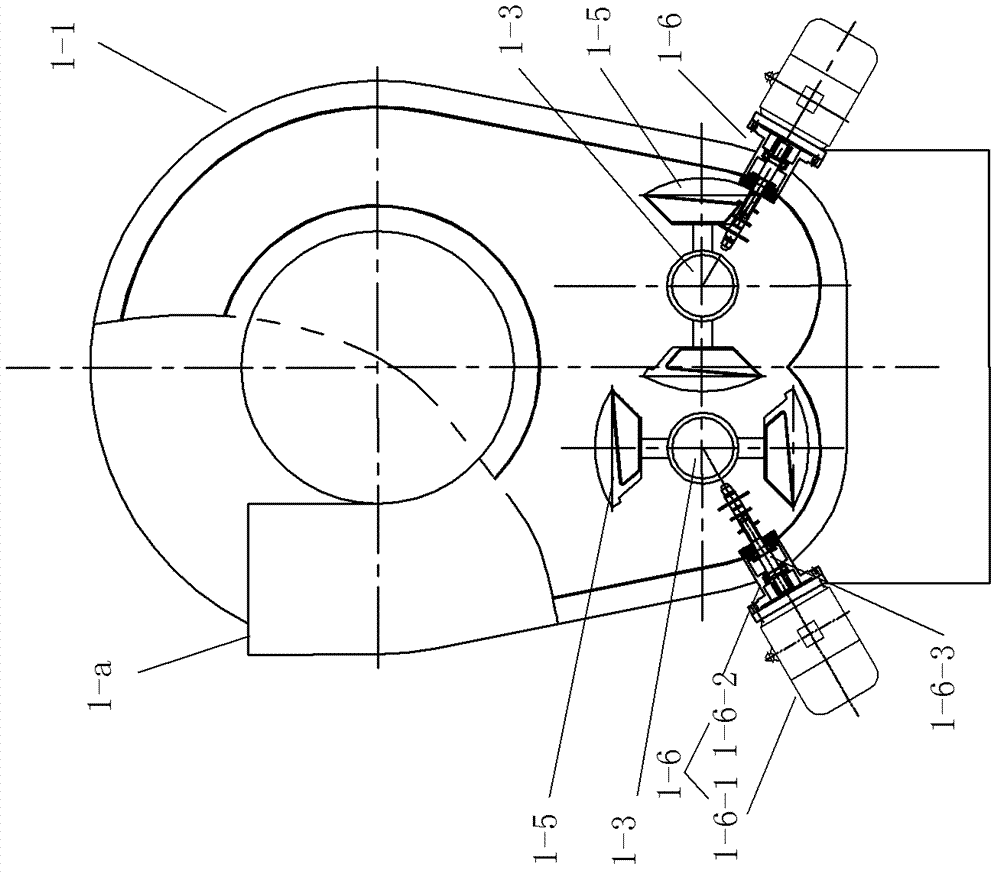
[0023] The main drying machine 1 has a body 1-1 supported by a frame 1-10, the upper part of the main drying machine 1 is arc-shaped, and the bottom is W-shaped. The upper part of the body cavity is provided with an airflow guide 1-2, and the space behind the body cavity behind the airflow guide 1-2 is a swirl chamber 1-f. The airflow guide 1-2 includes a core tube 1-2-1 and a spiral band 1-2-2 fixed on the core tube 1-2-1, and the spiral groove becomes a spiral airflow channel 1-e, and the spiral airflow channel The rear end of 1-e communicates with swirl chamber 1-f, and the airflow guide 1-2 is fixed by fixing the upper half edge of the spiral belt 1-2-2 on the inner wall of the body cavity.
[0024] The lower part of the body cavity is provided with a pair of stirring shaft...
Embodiment 2
[0030] The difference between embodiment 2 and embodiment 1 is that the compound condensation device 4 taken is different, see Figure 12 , compound condensing device 4 with inner finned tube condenser 4-4, gas-liquid separator 4-5 and liquid collection tank 4-6, liquid collection tank 4-6 is equipped with tube and tube cooler 4-7 . The above-mentioned inner finned tube condenser 4-4 and the gas-liquid separator 4-5 are connected to the liquid collecting tank 4-6 and communicate with the liquid collecting tank 4-6, and the hot air inlet 4-j of the composite condensing device 4 It is arranged on the top of the condenser 4-4, and the cold air outlet 4-h of the composite condensing device 4 is arranged on the top of the gas-liquid separator 4-5. The liquid collecting tank 4-6 is provided with a rectifying tower.
PUM
 Abstract
Description
Claims
Application Information
 - R&D Engineer
- R&D Manager
- IP Professional
- Industry Leading Data Capabilities
- Powerful AI technology
- Patent DNA Extraction
Browse by: Latest US Patents, China's latest patents, Technical Efficacy Thesaurus, Application Domain, Technology Topic, Popular Technical Reports.
© 2024 PatSnap. All rights reserved.Legal|Privacy policy|Modern Slavery Act Transparency Statement|Sitemap|About US| Contact US: help@patsnap.com