
Electric lifting roll brush device

A rolling brush and electric technology, applied in the field of rolling brush devices, can solve the problems of low adjustment accuracy, poor cleaning effect, and large time consumption, and achieve the effects of improving adjustment accuracy, reducing manual adjustment time, and convenient operation and maintenance

Active Publication Date: 2012-12-19
无锡洲翔成套焊接设备有限公司
View PDF4 Cites 0 Cited by
  • Summary
  • Abstract
  • Description
  • Claims
  • Application Information

AI Technical Summary

Problems solved by technology

In actual use, according to the height or thickness requirements of the workpiece, it is necessary to flexibly adjust the relative height position between the roller brush and the upper surface of the workpiece. The previous adjustment method mainly relies on manual adjustment, which consumes a lot of time and reduces work efficiency. Low, and the adjustment accuracy is not high, resulting in poor cleaning effect

Method used


Image

  • Electric lifting roll brush device
  • Electric lifting roll brush device

Examples


Embodiment Construction

[0014] The present invention will be further described below in conjunction with specific drawings and embodiments.

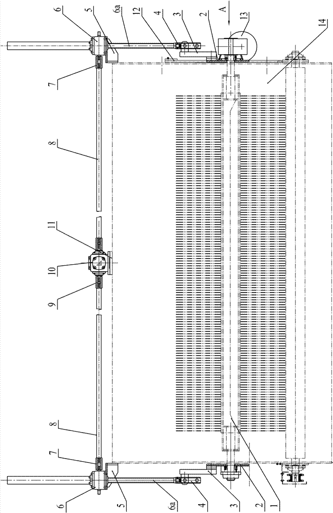
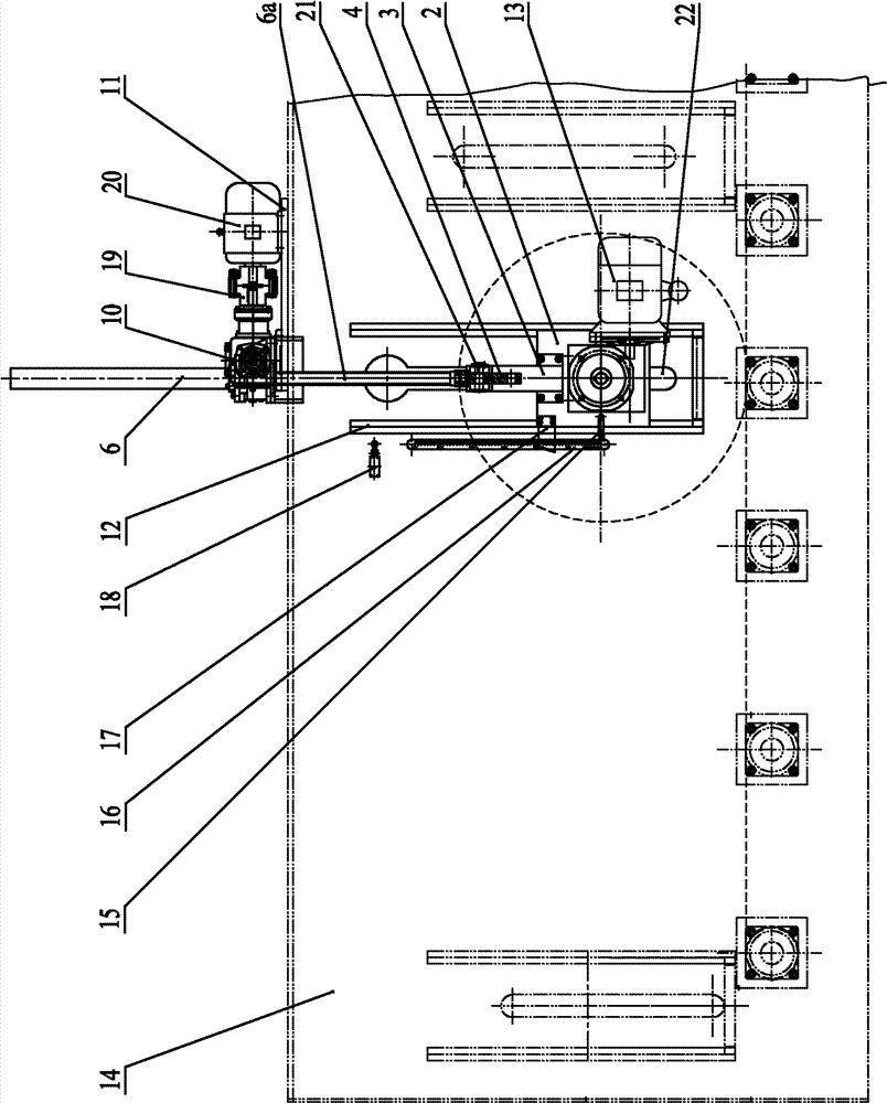
[0015] As shown in the figure, the electric lifting roller brush device in the embodiment mainly consists of roller brush 1, sliding plate 2, connecting bracket 3, connecting shaft head 4, elevator seat 5, screw elevator 6, second coupling sleeve 7, transition shaft 8. , The first coupling sleeve 9, T-type gear reducer 10, seat plate 11, sliding guide 12, roller brush motor reducer 13, pointer 15, ruler 16, limit bracket 17, travel switch 18, coupling 19, drive The motor 20 and the pin shaft 21 are composed; wherein, the screw lifter 6 is used as the lifting mechanism, and the driving motor 20 and the T-type gear reducer 10 form the lifting driving part.

[0016] Such as figure 1 As shown, the rolling brush 1 is arranged in the cleaning chamber 14. The left and right side walls of the cleaning chamber 14 are provided with vertical long mounting holes 22, and the two...


PUM


Abstract

The invention relates to an electric lifting roll brush device which comprises a roll brush arranged in a cleaning chamber. The device is characterized by also comprising a roll brush motor speed reducer, lifting mechanisms and a lifting drive component, wherein the left side wall and right side wall of the cleaning chamber are provided with vertical long mounting holes; two ends of the roll brush are respectively mounted on a sliding plate through a bearing after passing through the long mounting holes; the roll brush motor speed reducer is installed on a sliding plate at one side, and the output shaft of the roll brush motor speed reducer is connected with one end of the roll brush; the left side and right side of the cleaning chamber are respectively provided with one lifting mechanism; two sidling plates at two sides of the cleaning chamber are respectively connected to the lifting mechanisms at the same sides with the sliding plates; the two lifting mechanisms are respectively connected with the lifting drive component; the lifting drive components drive the lifting mechanisms to rotate; and the lifting mechanisms drive the two sliding plates at the two sides of the cleaning chamber and the roll brush to lift. The device provided by the invention has the advantages of inventive, compact and reasonable structure, high working efficiency and high regulating accuracy, the device is convenient to operate and maintain, and two ends of the roll brush are lifted synchronously and stably.

Description

Technical field [0001] The invention relates to a roller brush device on a shot blasting machine, in particular to an electric lifting roller brush device. Background technique [0002] Shot blasting machine is a device that uses high-speed projectiles thrown by a shot blasting machine to clean or strengthen the surface of castings. It can simultaneously shake out, remove cores and clean the castings. At present, the main objects of the shot blasting machine are foundry industry, petrochemical industry, Steel, steel structure parts, various castings, construction machinery, various types of steel, etc. The roller brush device is an important part of the shot blasting machine. It is used to clean the shots and recycle the shots. On the one hand, it prevents the shots from being taken out of the shot blasting machine and causes the waste of the shots; on the other hand, it avoids participation in the equipment. The shot has an impact on the workpiece being processed. In actual us...

Claims


Application Information

Patent Timeline
Patent Type & Authority Patents(China)
IPC IPC(8): B24C9/00
Inventor 徐旦徐惠忠周军
Owner 无锡洲翔成套焊接设备有限公司
Learn More