Eureka AIR delivers breakthrough ideas for toughest innovation challenges, trusted by R&D personnel around the world.

Integrated cable inlet-outlet sleeve

A technology for incoming and outgoing wires and bushings, applied in electrical components and other directions, can solve the problems of increasing the seal in place, increasing the air gap, increasing the width of the air box, etc., so as to reduce the risk of air leakage, reduce the width and size, and reduce the The effect of insulation distance

Inactive Publication Date: 2011-10-19
SHANGHAI PINGGAO TIANLING SWITCHGEAR CO LTD +1
View PDF5 Cites 3 Cited by
  • Summary
  • Abstract
  • Description
  • Claims
  • Application Information

AI Technical Summary

Problems solved by technology

[0004] 1. The insulators of the incoming and outgoing lines of each phase are independent, and the air gap between the phases affects the improvement of the insulation level between the phases. Often, as the voltage level of the switchgear increases, the air gap needs to be increased, thereby greatly increasing the width of the air box
Today, as land resources are increasingly tight, users urgently need to improve the space utilization of switchgear, and the wider switchgear size is gradually difficult to meet the needs of users in this respect;
[0005] 2. The inlet and outlet insulators of each phase are independent and small in size. When the inlet and outlet insulators or cable heads are improperly installed and the force is uneven, local deformation is likely to occur, causing gas leakage in the gas chamber, resulting in unnecessary failures during the operation of the switchgear. quality accidents;
[0006] 3. The insulators of the incoming and outgoing cables of each phase use a set of sealing rings, which increases the number of sealing rings and also increases the risk of insufficient sealing. It is also easy to cause gas leakage in the gas chamber and cause operation accidents of switchgear

Method used


Image

  • Integrated cable inlet-outlet sleeve
  • Integrated cable inlet-outlet sleeve
  • Integrated cable inlet-outlet sleeve

Examples


Embodiment Construction

[0014] The preferred embodiments of the present invention are given below in conjunction with the accompanying drawings to describe the technical solution of the present invention in detail.

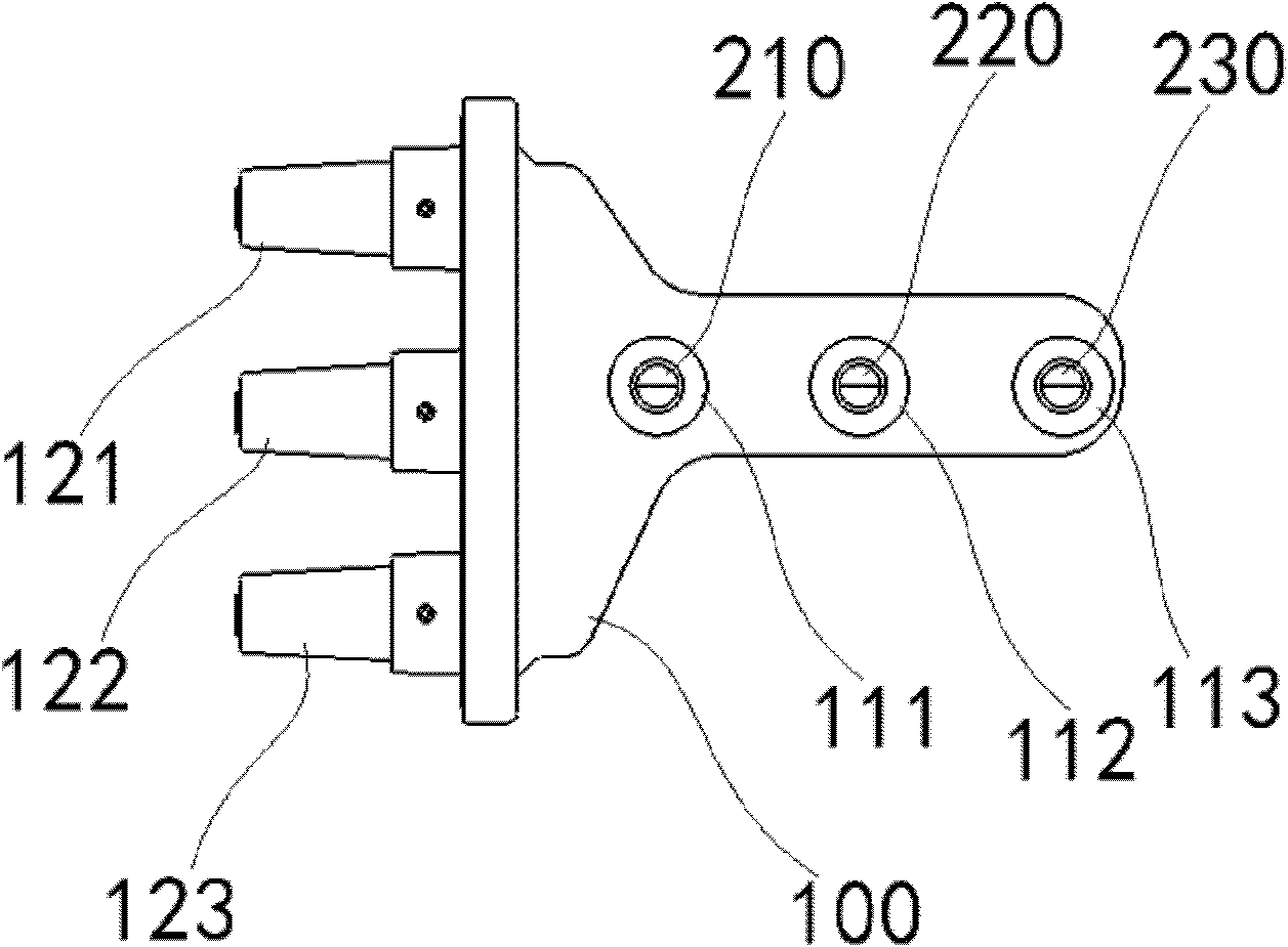
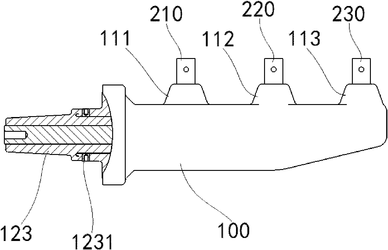
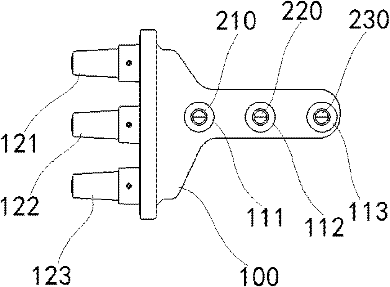
[0015] Such as figure 1 , figure 2 As shown, the present invention proposes an integrated cable inlet and outlet bushing, which includes an insulating bushing body 100 made of epoxy resin material. Three-phase busbars are arranged in the bushing body 100, which are A-phase busbars 230 and B-phase busbars respectively. The phase busbar 220, the C-phase busbar 210, and the three-phase busbar are poured into the bushing body at the same time, and the bushing body is provided with an inlet 111, an inlet 112, an inlet 113, an outlet 121, and an outlet 122 , Outlet 123, the inner end of the three-phase bus protrudes from the inlet, and the outer end protrudes from the outlet. When installing and using, the inner ends are respectively connected to the main circuit bus bars of each phase in th...


PUM


Abstract

The invention provides an integrated cable inlet-output sleeve, which comprises an insulated sleeve body made of epoxy resin, wherein three-phase buses are arranged in the sleeve body; the three-phases buses are simultaneously poured in the sleeve body; an inlet hole and an outlet hole are formed in the sleeve body; inner end heads of the three-phases buses extend form the inlet hole and the external end heads of the three-phases buses extend from the outlet hole; the internal end heads are connected with each phase of main loop bus in a switch cabinet respectively and the external end heads are connected with a cable accessory head when the sleeve is installed and used; and an induction coil is arranged in the outlet hole. By application of the integrated cable inlet-output sleeve, three phases of inlet-outlet insulators are integrated, so that the insulated distance between conductors and the width of the switch cabinet are reduced; the risk of air leakage caused by local deformation of the inlet-outlet insulators resulted form the error installation is reduced; the number of sealing rings is reduced; and the sealing reliability is improved.

Description

technical field [0001] The invention relates to a cable bushing for a medium-voltage switchgear, in particular to an integrated cable inlet and outlet bushing. Background technique [0002] In the existing domestic medium voltage switchgear, for all switchgears with cable inlet and outlet insulators, the cable inlet and outlet insulators of each phase are usually independent of each other, and each phase cable inlet and outlet insulators use a set of sealing rings. Such a structure is convenient for installation, maintenance and replacement, and at the same time, the volume of a single inlet and outlet insulator is relatively small. [0003] This kind of structure with independent insulators for incoming and outgoing lines of each phase is technically very mature, but there are the following problems: [0004] 1. The insulators of the incoming and outgoing lines of each phase are independent, and the air gap between the phases affects the improvement of the insulation level...

Claims


Application Information

Patent Timeline
Patent Type & Authority Applications(China)
IPC IPC(8): H02G3/04
Inventor 廖汉钱立骁任苗佳
Owner SHANGHAI PINGGAO TIANLING SWITCHGEAR CO LTD
Why Eureka
Eureka Blog
Learn More