Clamp used for uniformly evaporating anti-reflection film on side surface of optical fiber

A technology of anti-reflection coating and fixture, which is applied in the field of semiconductor lasers, can solve problems that affect the life and reliability of lasers, laser damage, and affect the collimation efficiency of semiconductor lasers, and achieve the goal of improving collimation efficiency, reducing reflection, and wide application value Effect

Inactive Publication Date: 2013-06-19
INST OF SEMICONDUCTORS - CHINESE ACAD OF SCI
View PDF6 Cites 0 Cited by
  • Summary
  • Abstract
  • Description
  • Claims
  • Application Information

AI Technical Summary

Problems solved by technology

Generally, the refractive index of silica fiber is 1.458, the refractive index of air is 1, and the reflectivity is 3.5%. This will cause a part of the semiconductor laser to reflect from the surface of the fiber to the laser cavity surface, which not only affects the collimation efficiency of the semiconductor laser, but also easily causes Laser damage, affecting the life and reliability of the laser

Method used


Image

  • Clamp used for uniformly evaporating anti-reflection film on side surface of optical fiber
  • Clamp used for uniformly evaporating anti-reflection film on side surface of optical fiber
  • Clamp used for uniformly evaporating anti-reflection film on side surface of optical fiber

Examples


Embodiment Construction

[0027] In order to make the object, technical solution and advantages of the present invention clearer, the present invention will be described in further detail below in conjunction with specific embodiments and with reference to the accompanying drawings.

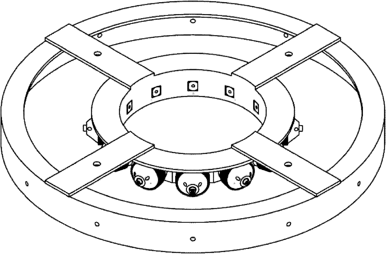
[0028] In order to achieve uniform coating on the side wall of the optical fiber, it is required that each optical fiber must rotate around its axis at a constant speed during the evaporation process, and because the coating rate at different positions in the coating chamber is different, the optical fiber is also required to be rotated during the evaporation process. Rotate around the center of the coating frame to ensure the uniformity of its film layer.

[0029] Such as Figure 5 As shown, the fixture provided by the present invention for uniformly evaporating the anti-reflection coating on the side of the optical fiber includes the upper half and the lower half, and the optical fiber held by the fixture rotates in the...


PUM

PropertyMeasurementUnit
refractive indexaaaaaaaaaa
reflectanceaaaaaaaaaa

Abstract

The invention discloses a clamp used for uniformly evaporating an anti-reflection film on the side surface of optical fiber, comprising an upper half part and a lower half part. The optical fiber clamped by the clamp rotates by adopting the mode of the combination of revolution and rotation in the coating process, wherein the upper half part is connected with a rotating part of a coating machine,and the rotating part of the coating machine drives the upper half part to rotate, so that the optical fiber clamped by the side surface of the upper half part rotates surrounding the center of the clamp so as to form the revolution; and the lower half part is connected with a body of the coating machine, and keeps still when the upper half part rotates, a gear track on the surface of the lower half part forces a part of the upper half part for clamping the optical fiber rotates synchronously when rotating along with the upper half part so as to form the rotation. By utilizing the clamp, the reflection of the optical fiber on the section of laser is reduced, the collimation rate of the optical fiber on a laser is improved, and the reliability of the laser is improved. Simultaneously, the clamp also can be used for coating on the side walls of other columnar objects, and has wide application values.

Description

technical field [0001] The invention relates to the technical field of semiconductor lasers, in particular to a fixture for uniformly evaporating an anti-reflection film on the side of an optical fiber. Background technique [0002] Semiconductor lasers have been widely used in many fields, especially high-power LDs are widely used, and they are becoming increasingly active. In many areas of application in laser technology, beam quality is crucial. In the pumping of fiber lasers, the numerical aperture and focus point size of the pump light after convergence are required to be smaller than the numerical aperture and core diameter of the inner cladding of the double-clad fiber, otherwise the pump energy will be lost. Similarly, in the end pumping of laser crystal rods, in order to improve the pumping efficiency and achieve better mode matching, a small area of ​​the crystal end face is often strongly pumped, so it is also necessary to focus the pump light into a diameter of ...

Claims


Application Information

Patent Timeline
Patent Type & Authority Patents(China)
IPC IPC(8): C03C25/22
Inventor 赵懿昊李全宁王翠鸾刘素萍马骁宇
Owner INST OF SEMICONDUCTORS - CHINESE ACAD OF SCI
Why Eureka
Try Eureka