
Led backlight system

A technology of light source and light-emitting diode, which is applied in the field of backlight illumination source, and can solve problems such as distortion or artifacts, reduced resolution, and limited brightness adjustment range

Active Publication Date: 2011-10-12
APPLE INC
View PDF5 Cites 25 Cited by
  • Summary
  • Abstract
  • Description
  • Claims
  • Application Information

AI Technical Summary

Problems solved by technology

However, such a configuration may result in reduced resolution, distortion or artifacts, and / or limited brightness adjustment range

Method used


Image

  • Led backlight system
  • Led backlight system
  • Led backlight system

Examples


Embodiment Construction

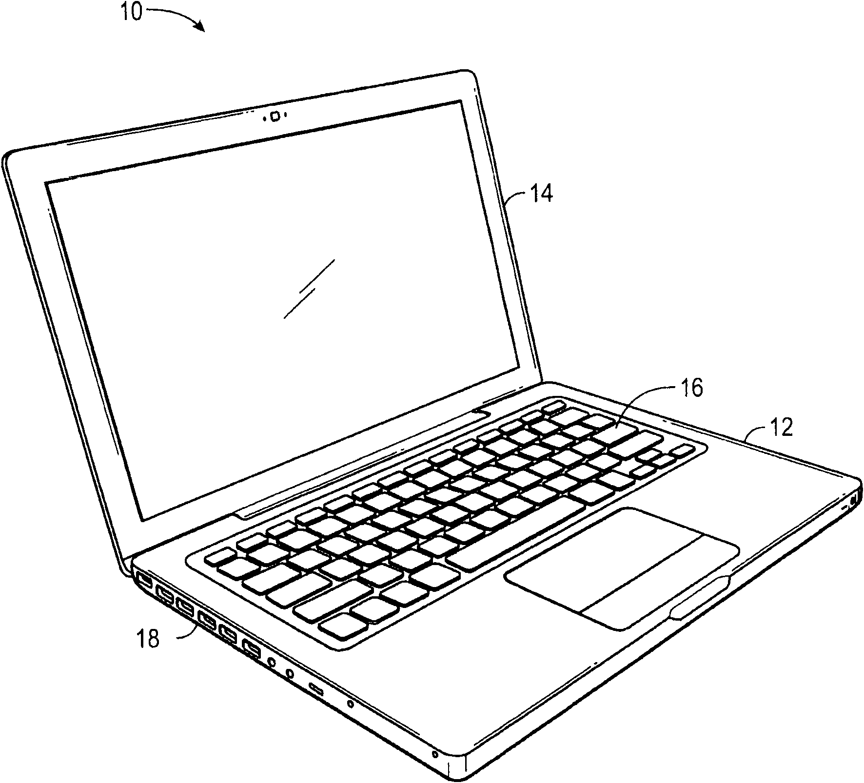
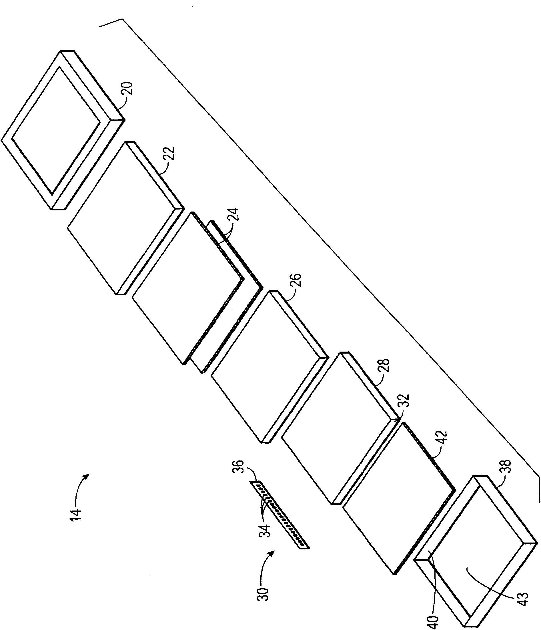
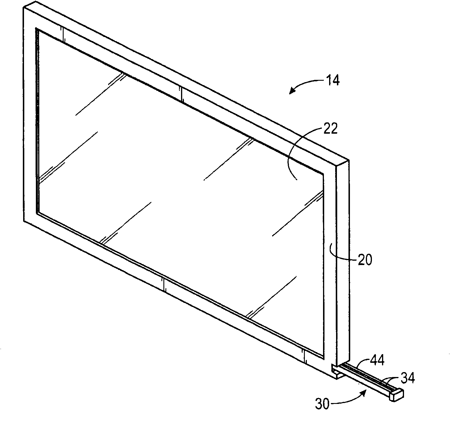
[0021] One or more specific embodiments are described below. In an effort to provide a concise description of these embodiments, not all features of an actual implementation are described in the specification. It should be understood that in developing any such actual implementation, such as in any engineering or design project, a number of implementation-specific decisions must be made to achieve the developer's specific goals, such as compliance with system-related constraints or business-related constraints, which may vary from implementation to implementation. In addition, it should be appreciated that such a development effort might be complex and time consuming, but nevertheless would be a routine undertaking of design, engineering, and manufacture for those of ordinary skill in the art having the benefit of this disclosure.

[0022] The present application generally relates to methods and systems for controlling a backlight of a display. A pulse width modulator (PWM) ...


PUM


Abstract

A method and system for modifying the pulse width modulation frequency for controlling the backlit illumination intensity of a liquid crystal display (14). The modified pulse width modulation frequency may be selected to reduce distortion in the display (14) while allowing for a wide range of dimming settings for the display (14). A pulse width modulation signal (95) may be also be phase shifted such that a string of light sources (110-115) may be sequentially activated to generate a effective frequency greater than that of the frequency of the pulse width modulation signal (95).

Description

technical field [0001] The present disclosure generally relates to controlling backlighting sources for liquid crystal displays. Background technique [0002] This section is intended to introduce the reader to various aspects of technology, which may be related to various aspects of the disclosure that are described and / or claimed below. This discussion is considered helpful in providing the reader with background information to facilitate a better understanding of various aspects of the present disclosure. Accordingly, it should be understood that these statements are to be read in this light, and not as admissions of prior art. [0003] Electronic devices increasingly include display screens as part of the device's user interface. It will be appreciated that display screens may be employed in a variety of devices, including desktop computer systems, notebook computers, and handheld computing devices, as well as a variety of consumer products, such as cellular telephones...

Claims


Application Information

Patent Timeline
Patent Type & Authority Applications(China)
IPC IPC(8): G09G3/34H05B44/00
CPCG09G2320/0233G09G2320/0247G09G2320/0633G09G2320/064G09G3/342Y02B20/30H05B45/38
Inventor P·M·汤普森F·金M·A·约希莫托
Owner APPLE INC
Learn More