
Inflator with means for increasing the output flow of pressurized gas

A technology of pressurized gas and output flow, which is applied in transportation and packaging, pedestrian/passenger safety arrangement, vehicle safety arrangement, etc., and can solve problems such as delay in opening, time for function realization, failure of suppression function, excessive stress, etc.

Active Publication Date: 2011-10-12
AUTOLIV DEV AB
View PDF6 Cites 2 Cited by
  • Summary
  • Abstract
  • Description
  • Claims
  • Application Information

AI Technical Summary

Problems solved by technology

[0006] However, if the flow output is too high, the bladder container and lid are overstressed during the first milliseconds of function of the inflator
[0007] If the output flow is too low, the opening is slow, and the function realization time and the suppression function cannot be realized

Method used


Image

  • Inflator with means for increasing the output flow of pressurized gas
  • Inflator with means for increasing the output flow of pressurized gas
  • Inflator with means for increasing the output flow of pressurized gas

Examples


Embodiment Construction

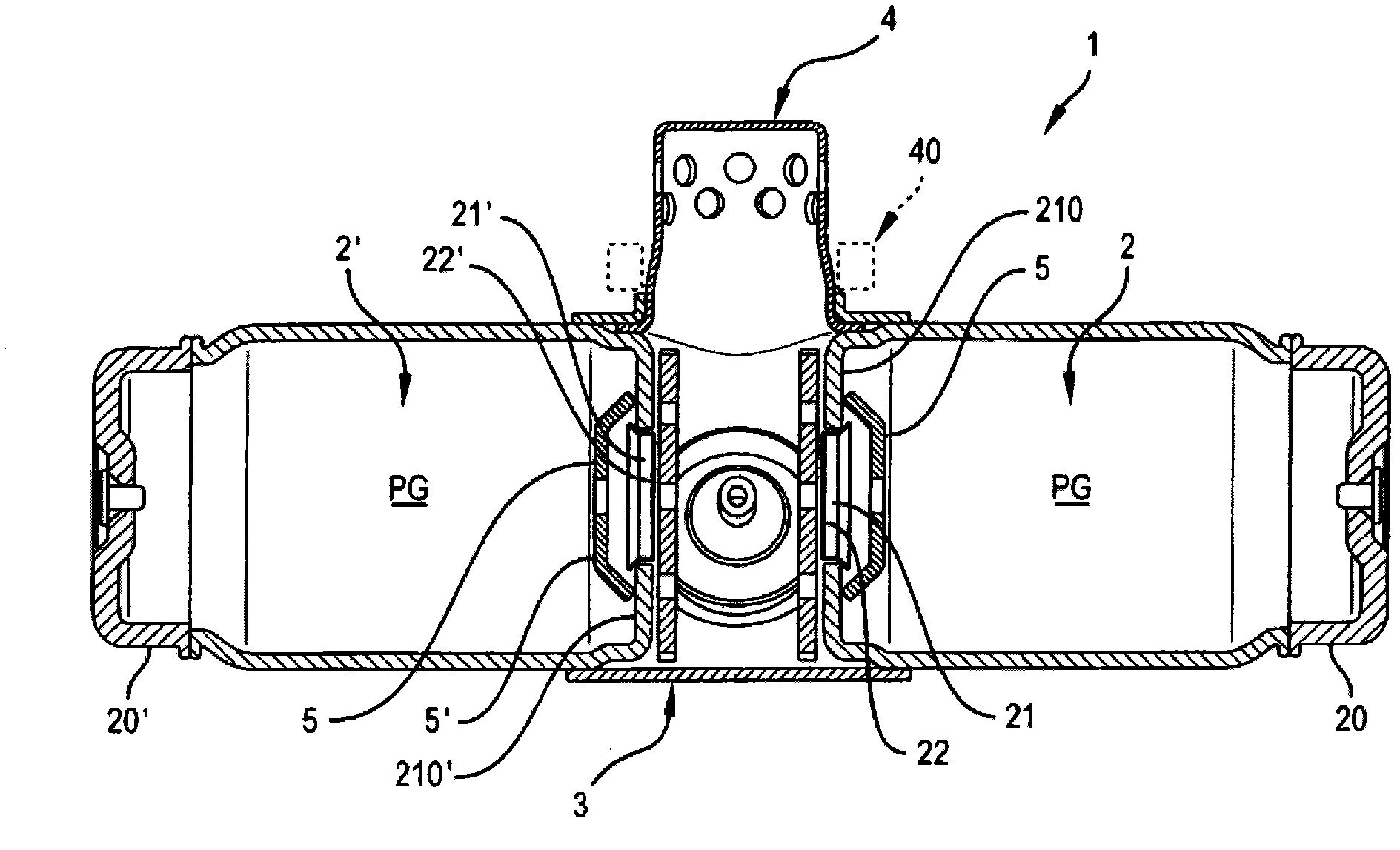
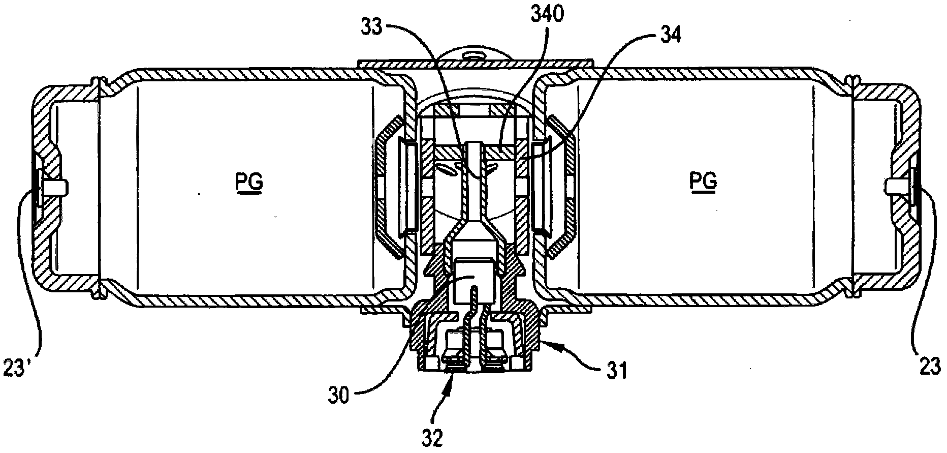
[0039] exist figure 1 and 2 The inflator 1 shown above has a known construction. The inflator 1 comprises a central housing 3 provided with an electrically activated igniter 30 mounted on a holder 31 and equipped with a shunt ring 32 .

[0040] In the chamber defined by this housing, and more precisely on the igniter, a piston 33 is mounted. The function of the piston 33 will be explained below.

[0041] The housing 3 communicates with a diffuser 4 which may be equipped with a sealing ring 40 .

[0042] Two cylindrical pressure vessels or gas chambers 2 and 2' are mounted on the casing 3. Containers 2 and 2' are adapted to receive gas under pressure PG. One of the opposite ends of the containers 2 and 2' is closed by an end cap 20 / 20' equipped with a plug 23 / 23'.

[0043] The wall 210 / 210' of the second end of the containers 2 and 2' has a hole 21 / 21' which is normally closed by a foil 22 / 22' on the outside of the container and fixed to the wall 210 / 210' . This fo...


PUM


Abstract

The invention relates to an inflator for an air-bag, which comprises at least one pressure vessel (2) containing pressurised gas, mounted on a housing which receives gas from said vessel (2) and direct it to the air-bag to be inflated, via an aperture (21 ) formed in a wall (210) of said vessel (2), this aperture (21 ) being normally closed by a foil (22) fixed on the wall (210), at the outside of the vessel (2), which breaks when a predetermined pressure is reached in said housing, characterized in that said vessel (2) contains means (5) for increasing the output flow of pressurized gas through said aperture (21 ) while the delta pressure between the inside of said vessel (2) and said housing decreases.

Description

technical field [0001] The present invention relates to an inflator for an air bag comprising at least one pressure vessel containing gas under pressure and mounted on a housing which receives gas from said vessel through an aperture and said gas is directed to said bladder to be inflated, said hole is formed in the wall of said container, which hole is normally closed by a foil on the outside of said container and fixed to said wall, The foil ruptures when a predetermined pressure is reached in the housing. Background technique [0002] An inflator of this type is disclosed in US-A-6,672,616. [0003] In this inflator, an igniter mounted on a holder generates hot gas to move an actuating member in a predetermined direction, the actuating member having a tapered surface acting on inclined surfaces of two open members, which Thus moving apart ruptures the foil of each container allowing gas to flow into the bladder. [0004] Such inflators cause difficulties with regard to...

Claims


Application Information

Patent Timeline
IPC IPC(8): B60R21/268B60R21/26
CPCB60R21/268B60R2021/26094B60R2021/2685
Inventor 马茨·约翰松洛朗·科斯特卡尔德马埃尔·舍瓦利耶
Owner AUTOLIV DEV AB
Learn More