
Textile machine

A technology of textile machines and blowers, which is applied in the direction of textiles and papermaking, can solve problems such as energy loss, and achieve the effect of avoiding energy loss

Active Publication Date: 2015-03-18
OERLIKON TEXTILE GMBH & CO KG
View PDF11 Cites 0 Cited by
  • Summary
  • Abstract
  • Description
  • Claims
  • Application Information

AI Technical Summary

Problems solved by technology

In this case, an excessive suction of steam in a heating device leads to a high air displacement and leads to a considerable energy loss in the heating device

Method used

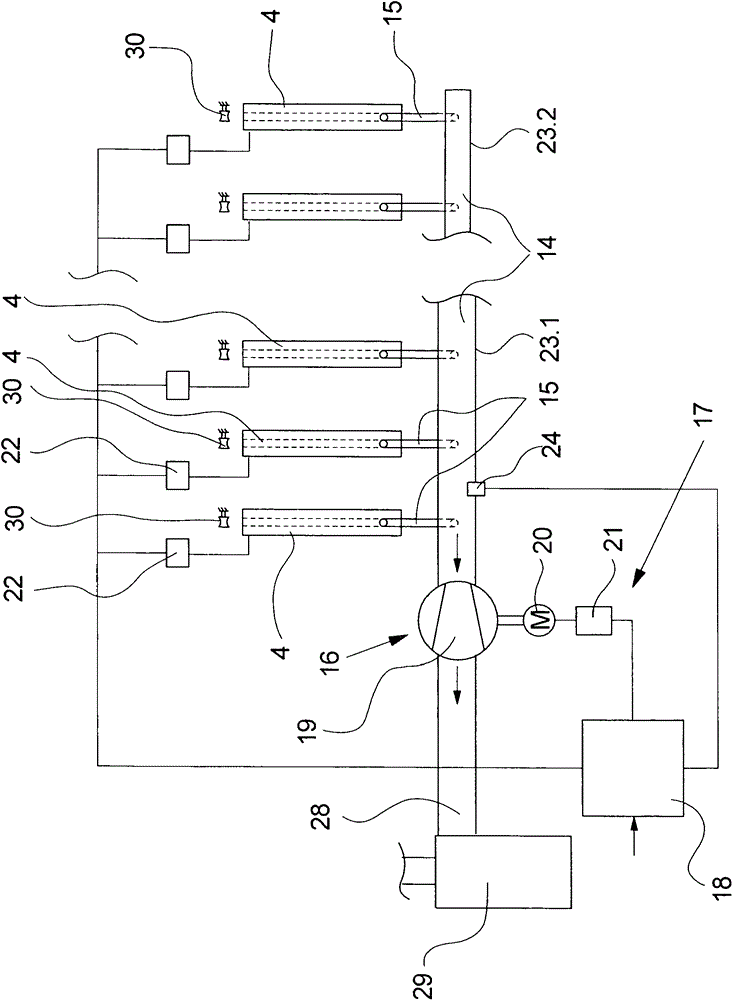

Image

  • Textile machine
  • Textile machine
  • Textile machine

Examples


Embodiment Construction

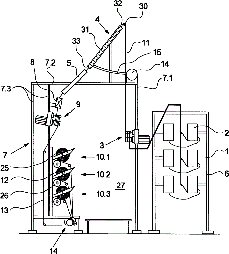
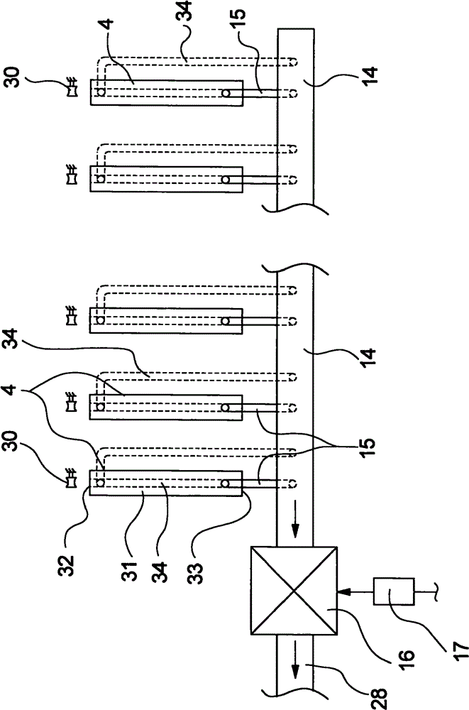
[0023] figure 1 and 2 A first embodiment of a textile machine according to the invention is shown in . figure 1 shows a cross-section of a textile machine, while in figure 2 shows a partial view from above of several heating devices arranged side by side in a machine. The following description applies to both figures unless otherwise stated with respect to one figure.

[0024] figure 1 The cross-sectional view shown in shows the spinning process (Fadenlauf) in a processing station in which the yarn is withdrawn from the yarn supply bobbin, guided, crimped, stretched and wound into a bobbin. The process devices required for this purpose are arranged in a multi-part frame 7 for the spinning process which partly surrounds a process walkway 27 . Textile machine along the longitudinal direction (in figure 1 , where the drawing plane is equal to the transverse plane) has multiple processing stations in order to simultaneously texturize and draw large numbers of yarns side by ...


PUM


Abstract

The invention relates to a textile machine, which comprises a plurality of yarn processing stations for processing yarn. In order to heat yarn, a plurality of heating devices are arranged for each of the yarn processing stations. The heating devices are connected with suction pipes respectively via their respective inhale pipes so as to suck out the steam. The suction pipeline is connected with a negative pressure source, wherein a control instrument is arranged for adjusting the suction strength. The control instrument directly applies on the negative pressure source so as to realize the stepless adjustment of the suction strength of the steam.

Description

technical field [0001] The invention relates to a textile machine according to the preamble of claim 1, comprising a plurality of processing stations for processing the yarn. Background technique [0002] During the further processing of the synthetic multifilament yarn, in order to modify the structure of the fiber, for example by a texturing process, it is generally known to subject the yarn to a heat treatment in order to soften the thermoplastic material of the fiber. The yarns are guided individually or in multiples through the heating device. Steam is generated during the heating of the yarn, which is formed from volatile components of the yarn, in particular the impregnation liquid. Such vapors cause a considerable pollution and environmental burden, so that the vapors are usually discharged immediately after their formation. The heating device provided in the textile machine is therefore connected to the central suction line via the suction line. For this purpose,...

Claims


Application Information

Patent Timeline
Patent Type & Authority Patents(China)
IPC IPC(8): D02G1/02D02J13/00
CPCD02J13/001D02G1/0266
Inventor J·斯特罗韦尔M·赫茨贝格
Owner OERLIKON TEXTILE GMBH & CO KG
Learn More