
Method for inspecting complex space integration position of steering knuckle type part

An inspection method and steering knuckle technology, applied in the inspection field of complex space comprehensive location, can solve the problems of inability to realize inter-process inspection, low requirements on the skill quality of operators, low inspection efficiency, etc., and meet the requirements of difficult measurement and worker quality. The effect of not high and fast detection speed

Inactive Publication Date: 2011-10-05
洛阳古城机械有限公司
View PDF2 Cites 12 Cited by
  • Summary
  • Abstract
  • Description
  • Claims
  • Application Information

AI Technical Summary

Problems solved by technology

[0009] The purpose of the present invention is to propose a method for inspecting complex spatial comprehensive positions of steering knuckle parts, so as to solve the phenomenon that the existing inspection methods cannot realize the inspection between processes or the inspection efficiency is low, and the requirements for the skills of the operators are not high

Method used


Image

  • Method for inspecting complex space integration position of steering knuckle type part
  • Method for inspecting complex space integration position of steering knuckle type part
  • Method for inspecting complex space integration position of steering knuckle type part

Examples


Embodiment Construction

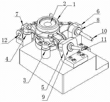
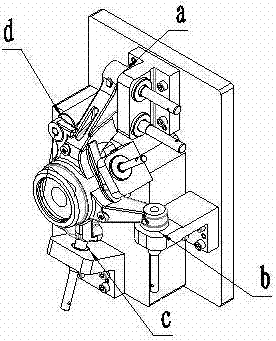
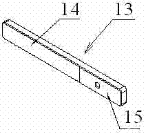
[0025] Combine figure 1 , figure 2 with image 3 , The inspection method of the complex spatial integrated position of the steering knuckle parts of the present invention, firstly, the main positioning hole of the inspected part 1 is correspondingly placed on the positioning shaft 2 fixedly connected to the base, and the other positioning of the inspected part 1 The holes correspond to the positioning pins fixed on the base 3 and positioning pins 4 on, so as to realize positioning axis 2, positioning pin 3 and positioning pins 4 Determine the only position of the inspected part 1 to fix the inspected part 1. If necessary, a movable pressing plate can be used to press the inspected part; secondly, the latch 10. Bolt 11 and latch 12 Insert the bushes separately 8 and bushing 9 in the guide hole, bolt 10. Bolt 11 and latch 12 is divided into the support on the base of the fixed connection 5. Support 6 and support 7 on; latch 10. Bolt 11 and latch 12 Slide in the b...


PUM


Abstract

The invention, which belongs to the machining inspection technology, discloses a method for inspecting an complex space integration position of a steering knuckle type part. The method includes a step of determining an only position of the part which needs to be inspected in a testing fixture. The step comprises that: a main locating hole of the inspected part is corresponding to a locating shaft which is fixed with a pedestal; other locating holes of the inspected part are corresponding to locating pins which are fixed with the pedestal so that the only position of the inspected part can be determined by the locating shaft and the locating pins. The method includes the step of inspecting a position relation of each hole of the inspected part. The step comprises that: latches are inserted into guide holes liners of bearings, wherein the bearings are fixed with the pedestal; the latches are slide in the liners of the bearings and whether the latches can pass through the holes of the inspected part is determined. The method also includes the step of inspecting distances between every surface and the position relations of every surface of the inspected part. The step comprises that: a feeler gauge is placed in a gap of the inspected part and a bearing surface and in a gap of the inspected part and locating pin surfaces and whether the feeler gauge can be placed into is determined. By using the method, inspections in working operations can be realized. And inspection efficiency is high. Operators do not need high skill quality.

Description

Technical field [0001] The invention belongs to machining inspection technology, and mainly relates to an inspection method for inspecting the complex spatial integrated position of knuckle parts. Background technique [0002] For the inspection of the spatial position of the parts that need to be inspected, the traditional method is to inspect with a dial indicator on the platform or inspect with a three-coordinate measuring machine; for the parallelism of the plane and the plane, the perpendicularity of the plane and the hole, the hole and the hole There are several traditional inspection methods for the position degree and the distance from the plane to the plane or the plane to the center of the hole: [0003] 1. Check the parallelism between the plane and the plane. The usual inspection method is to locate on a plane on the platform and use a dial indicator to check the parallelism of the plane at the other end; [0004] 2. The perpendicularity of the inspection plane to the h...

Claims


Application Information

Patent Timeline
IPC IPC(8): G01B5/25G01B5/14
Inventor 王新乐王永涝
Owner 洛阳古城机械有限公司
Learn More