
Water spouting device

A technology of water volume and outlet, which is applied in water supply equipment, indoor sanitary pipeline installations, buildings, etc. It can solve the problems of complicated operation, reduced sense of use, and low comfort of use, and achieve the effect of suppressing water splashing

Active Publication Date: 2011-10-05
TOTO LTD
View PDF6 Cites 17 Cited by
  • Summary
  • Abstract
  • Description
  • Claims
  • Application Information

AI Technical Summary

Problems solved by technology

[0011] Therefore, the user operates the water spouting device according to his own feeling to achieve high-flow water supply. As a result, when the total amount of spit out (equivalent to the actual water volume and air bubble volume) is felt to be much larger than the user's intended water volume, the air bubbles are mixed in. When pouring water, the sense of volume of spouting water is indeed improved, but when pouring water into cups and vases, due to the strong water force, it will form a return flow and overflow, so that only half of the capacity of the cup can be poured into the water
Furthermore, even if the cup or vase is consciously filled with half of the water, it is actually filled with air bubble injection water that increases due to the air bubbles. The case where a smaller amount of water is injected
In addition, in addition to filling cups and vases with water, it will also damage the basic purpose of reducing the sound of water splashing when spouting water into sinks and washbasins, and suppressing splashing of water at this time.
[0012] In order to avoid the above-mentioned problems, if the user has to finely adjust the spouting water volume, the operation will be complicated and the subtle feeling must be realized, so there is a possibility that the usability will be significantly reduced.
In addition, the opening degree of the air hole can be manually adjusted corresponding to the increase of the spouting water volume, so as to increase the air bubble mixing rate at low flow rate and suppress the air bubble mixing rate at high flow rate, but this also requires complicated processing by the user. The comfort of use is extremely low

Method used


Image

  • Water spouting device
  • Water spouting device
  • Water spouting device

Examples


Embodiment Construction

[0069] Embodiments of the present invention will be described below with reference to the drawings. In order to facilitate understanding, the same reference numerals are used as much as possible for the same components in each figure, and repeated explanations are omitted.

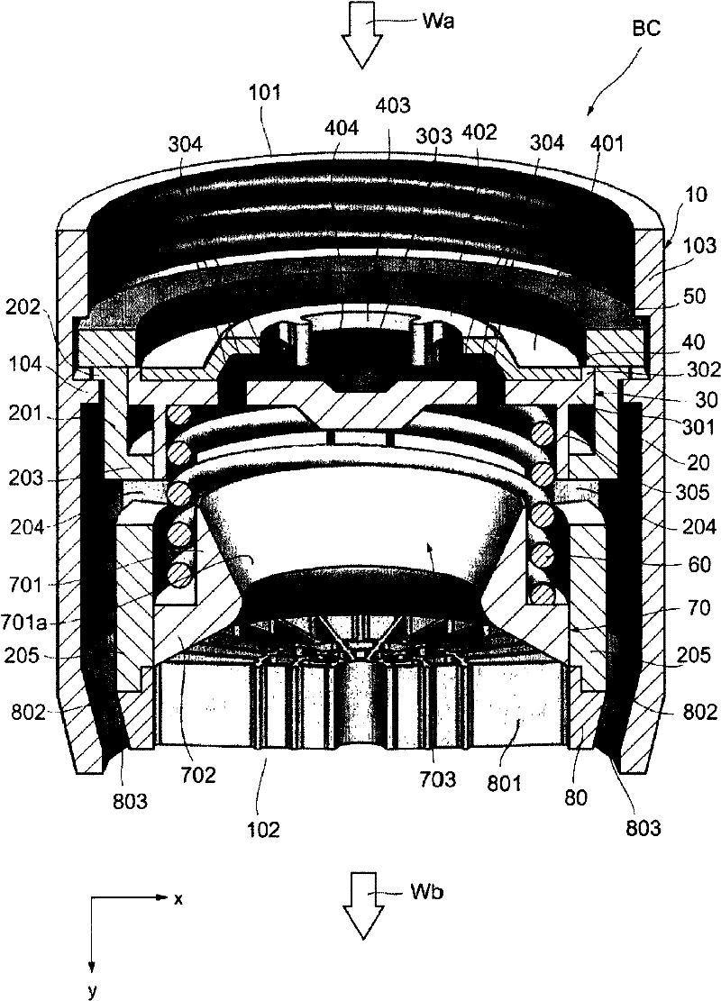
[0070] Regarding the spout cap (water spout device) of the first embodiment of the present invention, refer to figure 1 Be explained. figure 1 A perspective view of the faucet device FC as the water spouting device is shown at the right. The water cock device FC is installed at washbasins, washbasins, sinks, etc., and spits water toward the basins for storing and receiving water. The water faucet FC is attached to the periphery of the bowl, and is connected to a water pipe as a water supply source.

[0071] The faucet device FC has a standing portion B1, a spout portion B2, a spout handle HL, and a spout cap BC. The standing part B1 is a part installed on the fixed surface, and is installed and fixed i...


PUM


Abstract

A water spouting device which enables air bubble entrained water with an increased entrainment rate of air bubbles to be discharged at a low flow rate, the present water spouting device further enabling, at a high flow rate stage, prevention of discharge of air bubble entrained water with such a total amount as makes the user feel that the resultant amount of water significantly exceeds that intended by the user. A spout cap (BC) serving as the present water spouting device includes a pressure reducing portion (30) serving as an entrainment rate adjusting portion to adjust the entrainment rate of air bubbles entrained in air bubble entrained water in an air bubble entraining portion (703). The pressure reducing portion (30) serving as the entrainment rate adjusting portion increases the entrainment rate until inflow water from an inflow port (101) reaches a predetermined flow rate, and suppresses an increase in entrainment rate when the inflow water from the inflow port (101) exceeds the predetermined flow rate.

Description

technical field [0001] The present invention relates to a water jetting device capable of jetting water mixed with air bubbles. Background technique [0002] Conventionally, as a water spouting device, in order to reduce the sound of water splashing when spouting water into a sink or a washbasin, and to suppress splashing of water at this time, it has been proposed to spout air-bubbled water into the spouted water. In particular, in recent years, as described in Patent Document 1 below, a water discharge device has been proposed that increases the air bubble mixing rate from a low flow rate stage where the flow rate is relatively low in order to improve the volume of the discharged water. [0003] In the water spouting device described in the following Patent Document 1, a foam spouting member is provided at the front end of the spouting port of the faucet through a connector, and the foam spouting member has a flow path extending between the inflow port and the discharge po...

Claims


Application Information

Patent Timeline
Patent Type & Authority Applications(China)
IPC IPC(8): E03C1/084
CPCE03C1/084
Inventor 北浦秀和武田宏二工藤智博八板辽平
Owner TOTO LTD
Learn More