
Telescopic landing leg expanding mechanism for planetary probe

A technology for deploying mechanisms and detectors, which is applied to the landing device of space vehicles and the system for space vehicles to return to the earth's atmosphere, etc. It can solve the problems of complex structure of the expansion and locking mechanism, non-adjustable deployment radius of the landing legs, and inability to deploy the landing legs, etc. , to achieve the effect of simple structure, light weight and good structural rigidity

Active Publication Date: 2011-09-28
NANJING UNIV OF AERONAUTICS & ASTRONAUTICS
View PDF3 Cites 25 Cited by
  • Summary
  • Abstract
  • Description
  • Claims
  • Application Information

AI Technical Summary

Problems solved by technology

The pressing device must have a separate pressing point, and the pressing method is more complicated. In addition, if the scroll spring fails or breaks, the power to deploy will disappear, and the landing legs will not be able to deploy.
It can be seen that the traditional unfolding locking mechanism has complex structure and low reliability.
In recent years, some scholars have proposed some new soft landing locking mechanisms for planetary probes. The working methods of these mechanisms are generally "unlocking-unfolding-locking", and they are all disposable. The expansion radius is not adjustable

Method used


Image

  • Telescopic landing leg expanding mechanism for planetary probe
  • Telescopic landing leg expanding mechanism for planetary probe

Examples


Embodiment Construction

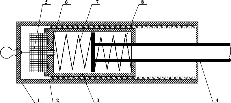
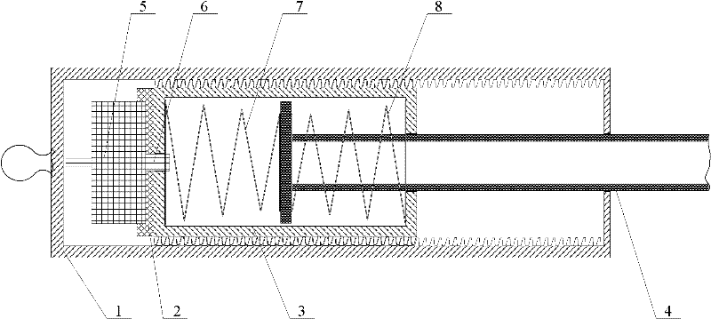
[0017] figure 1 It is a schematic diagram of the extension mechanism of the landing leg of the telescopic planetary probe. Reference figure 1 As shown, the telescopic planetary probe landing leg deployment mechanism includes a pillar outer cylinder 1, a pillar inner cylinder 3, and a piston cylinder 4. An inner thread is provided on the inner wall of the pillar outer cylinder 1, which is connected to the outer wall of the pillar inner cylinder 3. The upper end of the pillar inner cylinder 3 is provided with a rotating electric machine 5, the rotating electric machine 5 and the pillar inner cylinder 3 are connected by a linear bearing 2, and the output shaft 6 of the rotating electric machine is fixed with the pillar inner cylinder 3; the piston cylinder 4 is arranged at The inner part of the pillar inner cylinder 3 is placed in the middle of the pillar inner cylinder, and a tension buffer spring 8 and a compression buffer spring 7 are respectively placed between the piston cyl...


PUM


Abstract

The invention discloses a telescopic landing leg expanding mechanism for a planetary probe, comprising an outer support cylinder, an inner support cylinder and a piston cylinder; internal threads are arranged on the inner wall of the outer support cylinder and are matched with external threads on the outer wall of the inner support cylinder; a rotating motor is arranged on the upper end of the inner support cylinder; the rotating motor is connected with the inner support cylinder through a linear bearing; an output rotating shaft of the rotating motor is fixed with the inner support cylinder;the piston cylinder is arranged in the inner support cylinder; a tension buffering spring and a compression buffering spring are respectively arranged between the piston cylinder and two ends of the inner support cylinder; and the outer support cylinder, the inner support cylinder, the linear bearing, the piston cylinder, the rotating motor and the output rotating shaft are positioned on the sameaxial line. The expanding mechanism realizes locking function through threaded fit; the rotating motor drives the inner cylinder to rotate; the inner cylinder rotates outwards from the threads to eject the piston rod; the motor reversely rotates to reset the inner cylinder; the buffering mode is spring buffering; the expansion radius of the landing leg is controllable; the expanding mechanism is repeatedly used; furthermore, the expanding mechanism is simple in structure and high in reliability.

Description

Technical field [0001] The invention belongs to a telescopic deployment and locking mechanism for a planetary probe landing leg, which can be used repeatedly and can control the deployment radius of the landing leg. technical background [0002] The landing leg is an important part of the probe, which provides support for the probe to stably land on the interstellar surface. Due to the limitation of the vehicle, the landing leg must be able to be folded and compressed during the launch phase to meet the needs of the carrier envelope profile and improve the ability to withstand launch overload. When the probe flies to a certain trajectory, the compression device is unlocked, and the landing leg is expanded to a certain angle under the action of the unfolding drive device and then locked again, so as to obtain a larger supporting area while landing buffer, and improve the landing of the probe stability. [0003] The compression device and the locking device of the traditional Apoll...

Claims


Application Information

Patent Timeline
IPC IPC(8): B64G1/62
Inventor 聂宏林轻陈金宝柏合民陈萌博伟
Owner NANJING UNIV OF AERONAUTICS & ASTRONAUTICS
Learn More