
Cable supplying and rotating system

A technology for cable and supply equipment, which is applied in the field of cable supply and rotation systems, can solve the problems of occupying a large space, complex equipment structure, low efficiency of system power utilization, etc., and achieve the effect of simplifying the structure and reducing manufacturing costs

Active Publication Date: 2014-09-03
KOMAX HOLDING
View PDF8 Cites 0 Cited by
  • Summary
  • Abstract
  • Description
  • Claims
  • Application Information

AI Technical Summary

Problems solved by technology

[0004] In the prior art, since the cable supply equipment and the rotating equipment are separated from each other, both the cable supply equipment and the rotating equipment need to occupy a certain space. Therefore, the whole system has a large volume and needs to occupy a large space
[0005] In addition, in the prior art, since the cable supply equipment and the rotating equipment are separated from each other, the cable supply equipment needs a belt drive device for conveying cables, and at the same time, the rotating equipment needs a set of stick clamping device, resulting in the whole The system is complicated and the cost is too high
[0006] In addition, in the prior art, the drive belt of the belt drive device of the cable supply equipment is too long, therefore, it is necessary to set a plurality of pressure rollers in the middle of the drive belt, so as to press a pair of drive belts tightly together, This will also lead to the complexity of the whole system and high cost
[0007] In addition, in the prior art, the structure of the stick driving device of the rotating equipment is complex and needs to have at least three rotation axes, resulting in high cost and low system power utilization efficiency
[0008] In addition, in the prior art, the drive motor of the cable supply equipment is fixed on a fixed frame, and cannot be rotated to an inclined position together with the installation frame of the cable supply equipment. Therefore, the rotating shaft of the motor must adopt a flexible shaft, and the flexible shaft must be able to rigidly transmit the rotational motion, the use of this special flexible shaft will increase the installation difficulty and equipment cost
[0009] Moreover, in the prior art, due to the complex structure of the equipment, the work efficiency is not high and the detection accuracy is low

Method used


Image

  • Cable supplying and rotating system
  • Cable supplying and rotating system
  • Cable supplying and rotating system

Examples


no. 1 example

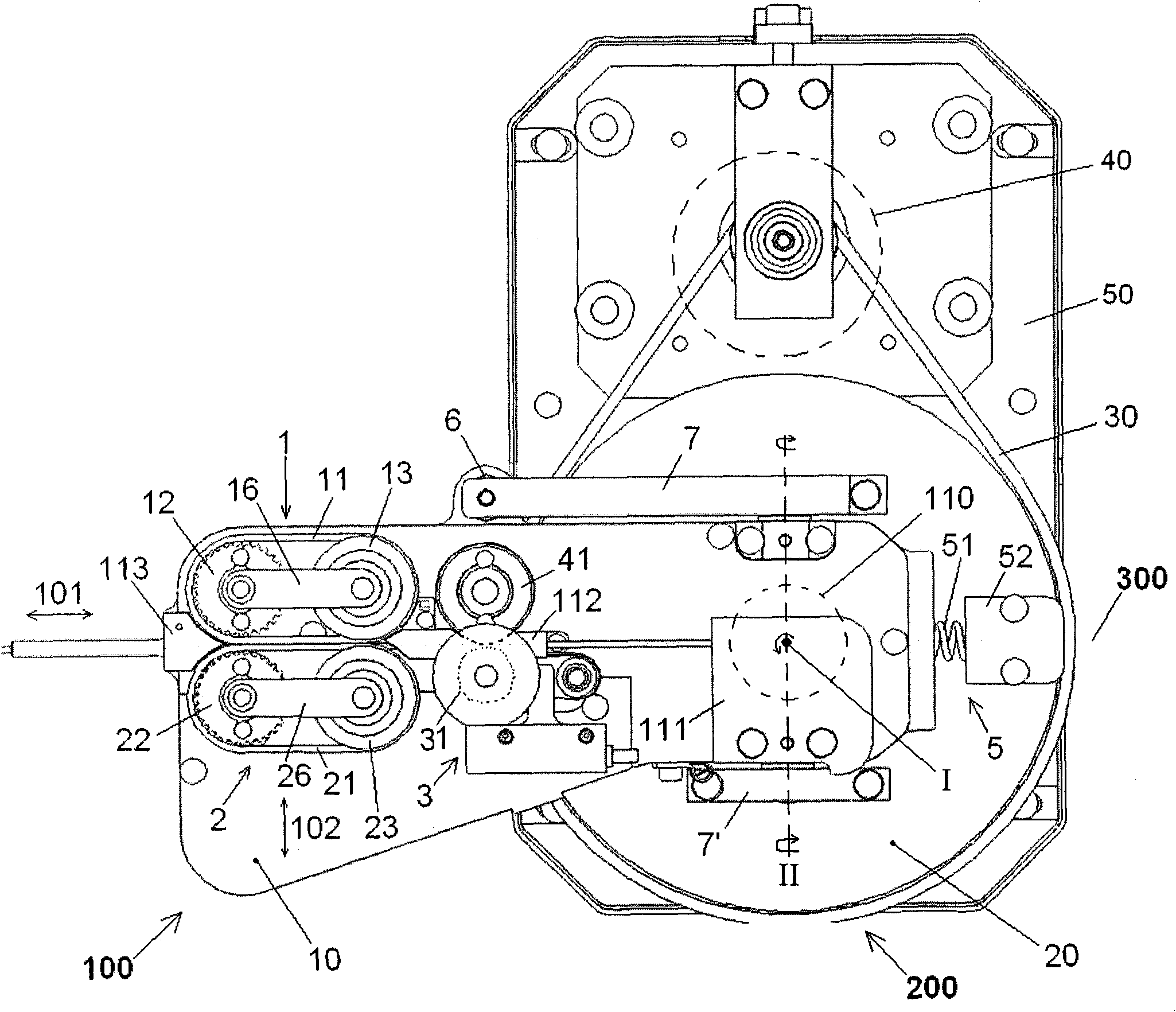
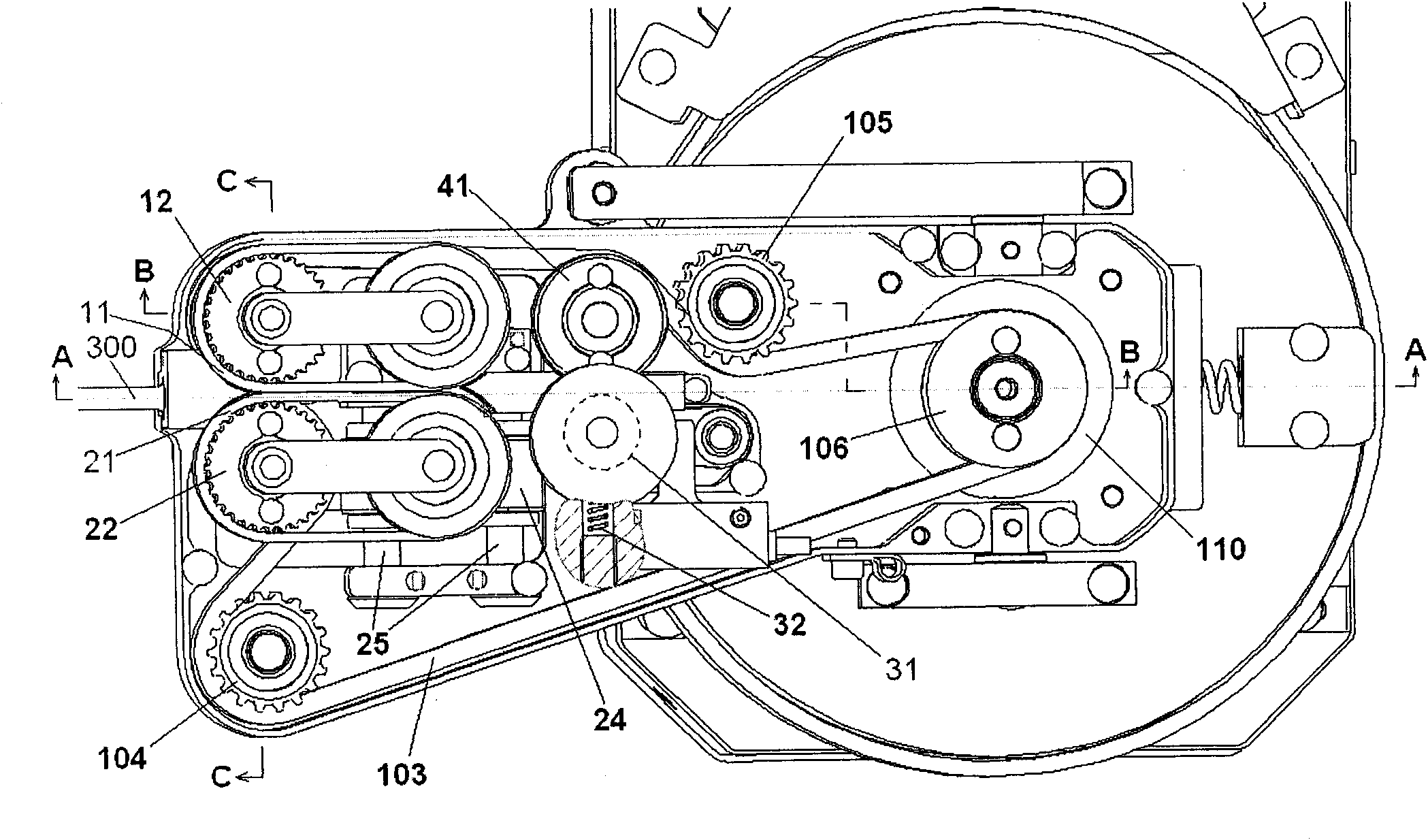
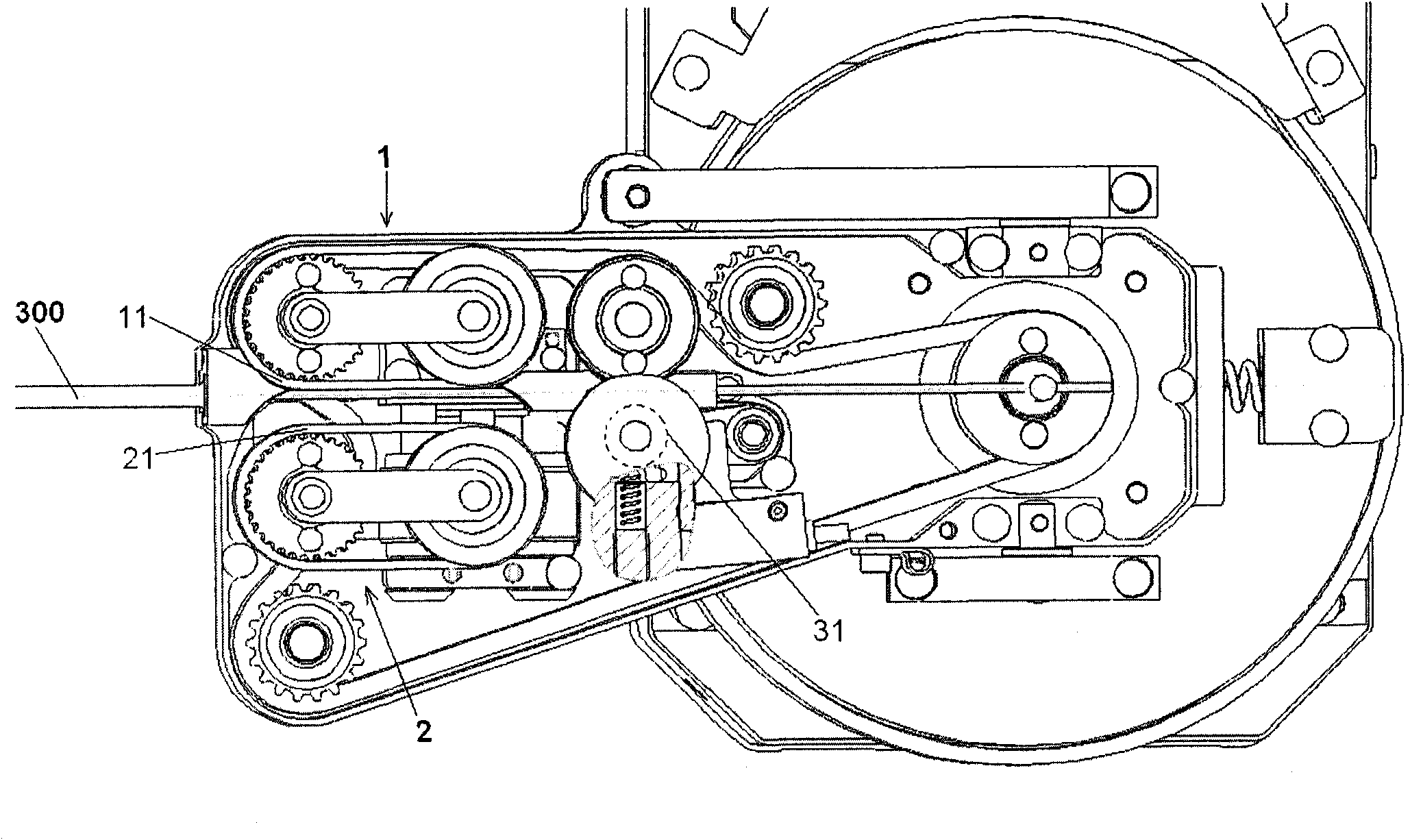
[0044] Figure 1 to Figure 7 A first embodiment of the cable feeding and rotating system of the present invention is shown.

[0045] figure 1 A top view of a cable feeding and rotating system according to a first embodiment of the invention is shown. Such as figure 1 As shown, in this embodiment, the cable supply and rotation system mainly includes a cable supply device 100 and a rotation device 200 . The cable supply device 100 is configured to supply a cable 300 of a predetermined length to a cable processing mechanism, such as a cable cutting mechanism (not shown). The rotating device 200 is used to rotate the cable supply device 100 to different positions, so as to perform other operations on the cable except cutting, for example, crimping a terminal on the cable end.

[0046] More specifically, in this embodiment, as figure 1 As shown, the cable supply device 100 mainly includes a pair of cable driving devices 1 and 2 facing each other and a cable length detecting de...

no. 2 example

[0088] Figure 8 A top view of a cable feeding and rotating system according to a second embodiment of the invention is shown.

[0089] Compared with the cable feeding and rotating system of the first embodiment, the cable feeding and rotating system of the second embodiment differs only in that a pair of friction rollers 12', 22' are used instead of one of the first embodiment. For belt drives 1, 2.

[0090] Apart from that, other structures of the cable feeding and rotating system of the second embodiment are completely the same as those of the first embodiment, therefore, for the purpose of brevity, the same parts can be referred to the previous Figure 1 to Figure 7 , which will not be described in detail here.

[0091] Specifically, in Figure 8 In the second embodiment shown, the fixed cable drive 1 comprises a first friction roller 12'; the movable cable drive 2 comprises a moving block 24 (see figure 2 ) and a second friction roller 22'.

[0092] Such as figure...


PUM


Abstract

The invention discloses a cable supplying and rotating system comprising cable supplying equipment and rotating equipment, wherein the cable supplying equipment is constructed to supply a cable of a preset length to a cable processing machine and comprises a pair of opposite cable driving devices for supplying the cable in a first direction and a cable length detecting device for measuring the supplied length of the cable; the rotating equipment is constructed to support the cable supplying equipment and drive the cable supplying equipment to rotate around a first rotating axis vertical to the first direction along with the rotating equipment; and the cable supplying equipment is further constructed to be capable of rotating around a second rotating axis vertical to the first direction and the first rotating axis. In the invention, because the cable supplying equipment is supported on the rotating equipment, the cable supplying equipment and the rotating equipment can share a set of driving device for clamping and conveying the cable and simultaneously need to rotate just by rounding the first rotating axis and the second rotating axis, and thus, the structure of the system is greatly simplified and the cost is reduced.

Description

technical field [0001] The present invention relates to a cable feeding and rotating system for supplying a predetermined length of cable to a cable processing mechanism (such as a cable cutting mechanism, etc.) and rotating the cable to other cable processing mechanisms (such as a cable terminal crimping mechanism, etc.) to perform other operations (such as cable terminal crimping operations). Background technique [0002] In the prior art, the cable supply device and the rotating device are separated from each other, and the cable supply device and the rotating device are arranged in series one after the other. In the following, a brief introduction will first be made to the working process of cutting, stripping and crimping terminals for cables using the aforementioned separate cable supply equipment and rotating equipment. [0003] The cable first enters from the inlet side of the cable supply device, and is clamped and transported to a cable length detection device by ...

Claims


Application Information

Patent Timeline
Patent Type & Authority Patents(China)
IPC IPC(8): H01R43/28H01R43/05H01R43/052
Inventor 朗格·汉斯熊秋慧
Owner KOMAX HOLDING
Learn More