
Multicore-fiber-based optical motor and micropump

Inactive Publication Date: 2011-09-14
HARBIN ENG UNIV
View PDF4 Cites 7 Cited by
  • Summary
  • Abstract
  • Description
  • Claims
  • Application Information

AI Technical Summary

Problems solved by technology

Laser optical tweezers are relatively bulky, difficult to move, and expensive

Method used


Image

  • Multicore-fiber-based optical motor and micropump
  • Multicore-fiber-based optical motor and micropump
  • Multicore-fiber-based optical motor and micropump

Examples


Embodiment Construction

[0029] The present invention is described in more detail below in conjunction with accompanying drawing example:

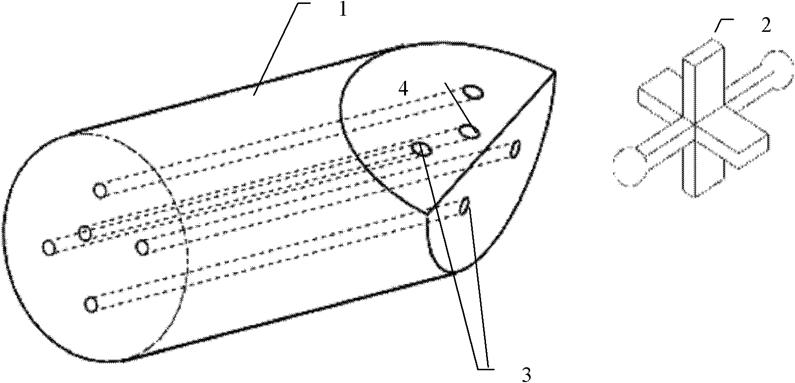
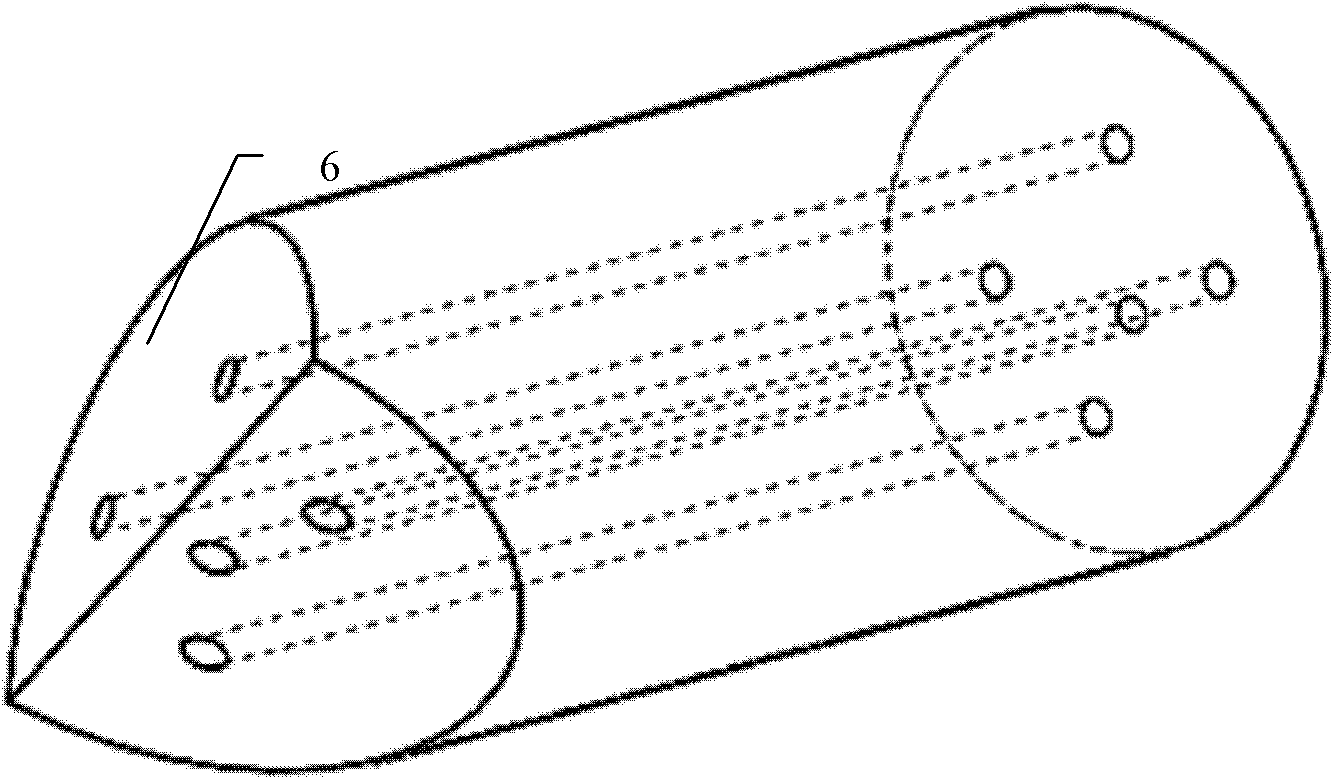
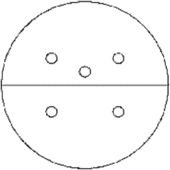
[0030] combine figure 1 , the optical motor based on the multi-core optical fiber of the present invention includes a multi-core optical fiber 1 and a micro-rotor 2 with a wedge-shaped front end; Figure 6-8 , the micro-rotor includes a sphere, a rotating shaft and wings, 3-8 wings are arranged on the rotating shaft, and two spheres are installed on both ends of the rotating shaft to form a micro-rotor with a symmetrical structure; the multi-core optical fiber with a wedge-shaped front end includes a The double-optical tweezers capture the sphere of the micro-rotor and act as two pairs of bilaterally symmetrical fixed-axis cores 3 , which also include a drive core 4 that emits outgoing light to drive the wings of the micro-rotor. The described front end is a wedge-shaped multi-core optical fiber, and the front end of the multi-core optical fiber is precisely proc...


PUM


Abstract

The invention provides a multicore-fiber-based optical motor and a micropump. The optical motor comprises multicore fibers with wedge-shaped front end and a micro rotor; the micro rotor comprises two sphere bodies, a rotating shaft and wings, wherein the wings are positioned on the rotating shaft, and the two sphere bodies are arranged at two ends of the rotating shaft to form the micro rotor with a symmetrical structure; and the multicore fiber with the wedge-shaped front end comprises two pairs of shaft fixing fiber cores and driving fiber cores, wherein the shaft fixing fiber cores are symmetrical at two sides and play a shaft fixing role in forming dual optical tweezers for capturing the sphere bodies of the micro rotor, and the driving fiber cores emit outgoing light to drive the wings of the micro rotor; two V-shaped grooves and dual U-shaped runners are machined on a glass substrate; the wedge-shaped multicore fiber is fixed in the V-shaped grooves; the micro rotor is placed ata U-shaped bending part of the dual U-shaped runners; and the micro rotor is driven by the multicore fiber with the wedge-shaped front end to rotate to drive fluid to flow to form the micropump. Compared with the traditional optical drive device, the optical motor has the advantages of small size, light weight, simple structure, low cost, easiness in operation, saved operation space, and the likeand can be widely applied to biological and chemical fields.

Description

technical field [0001] The invention relates to a micro-drive device. Specifically, it is a device in which a multi-core optical fiber applied in a micropump drives a microrotor to rotate. Background technique [0002] In recent years, Micro Total Analysis System (μTAS), also known as a laboratory built on a single chip, has set off a huge wave of research in the fields of medical research, biological application analysis and chemistry. Among them, the micropump is one of the most important parts to drive the microfluidic movement, so the design and preparation of the micropump is becoming more and more important. However, the previously fabricated micropumps were limited due to the volume formed by deformable membranes (M.A.Unger, H.P.Chou, T.Thorsen, A.Scherer and S.R.Quake, "Monolithic Micro-fabricated Valves and Pumps by Multilayer Soft Lithography," Science 288, 113 (2000)), so it is difficult to reduce its size. In addition, the micropump prepared in this way will p...

Claims


Application Information

Patent Timeline
Patent Type & Authority Applications(China)
IPC IPC(8): G02B6/24G02B6/02G21K1/00
Inventor 苑立波毕思思
Owner HARBIN ENG UNIV
Learn More