Radiating unit of directly-heated type electric heater and manufacturing method of radiating unit

A technology for a heat dissipation unit and an electric heater, applied in the field of electric heaters, can solve the problems of material waste cost, different degrees of close contact of the structure and dimensions, and the heat dissipation unit affecting the heat transfer effect, etc., so as to avoid material waste and a simple manufacturing method. Effect

Inactive Publication Date: 2011-09-14
刘春元 +1
View PDF12 Cites 7 Cited by
  • Summary
  • Abstract
  • Description
  • Claims
  • Application Information

AI Technical Summary

Problems solved by technology

[0003] The heat dissipation unit of the above-mentioned electric heating tube electric heater is composed of a heat dissipation profile and an electric heating tube, and there are the following practical problems: 1. The embedded joint of the electric heating tube and the heat dissipation profile adopts the existing expansion joint process. The degree of close contact is different due to the error of the size, and the heat dissipation unit with loose contact will seriously affect its heat transfer effect; Tubes are set repeatedly, resulting in material waste and increased costs

Method used


Image

  • Radiating unit of directly-heated type electric heater and manufacturing method of radiating unit
  • Radiating unit of directly-heated type electric heater and manufacturing method of radiating unit
  • Radiating unit of directly-heated type electric heater and manufacturing method of radiating unit

Examples


Embodiment Construction

[0027] The present invention will be further described below in conjunction with the embodiments and the accompanying drawings.

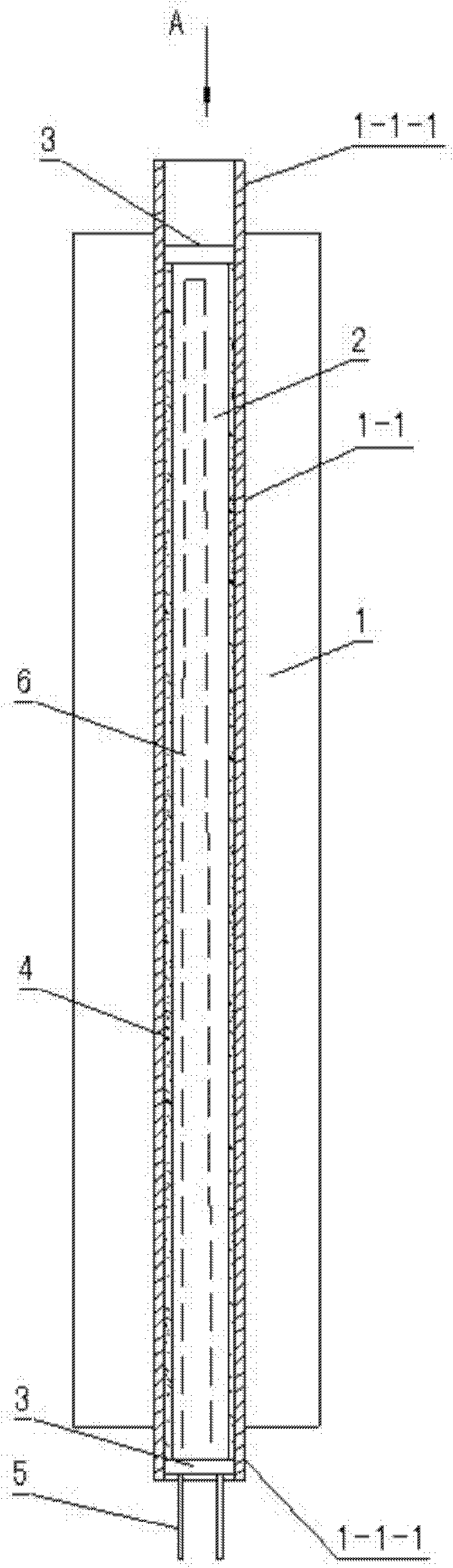
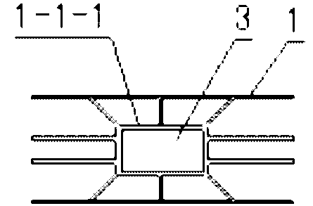
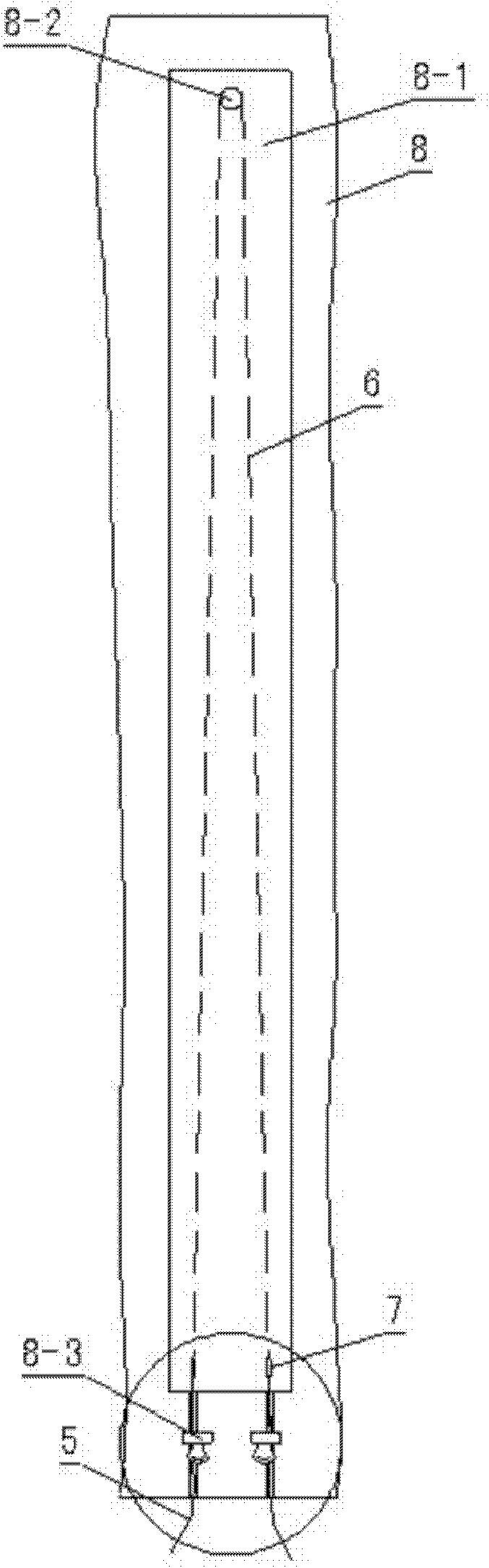
[0028] like figure 1 , 2 In the embodiment of the heat dissipation unit shown, the heat dissipation profile 1 is provided with a rectangular core tube 1-1, and the core tube is provided with a rod-shaped electric heating core 2, and the rod-shaped electric heating core is composed of an insulator, a spiral electric heating wire and a high temperature resistant sheath lead wire, The spiral heating wire 6 is reciprocally distributed in the insulator along the long axis direction of the insulator ( figure 1 shown in dashed lines). The insulator is also provided with a connecting portion where the spiral heating wire 6 and the lead wire 5 of the high temperature resistant sheath are connected by a metal connection sleeve 7 . The insulator is composed of bonded and solidified magnesia sand, the insulator and the core tube are filled with magnesia sand...


PUM


Abstract

The invention discloses a radiating unit of a directly-heated type electric heater and a manufacturing method of the radiating unit. A radiating sectional material of the radiating unit is provided with a core tube of which the section is rectangular, wherein a rod-like electric heat core is arranged in the core tube; the rod-like electric heat core consists of an insulator, spiral electric heat wires and high-temperature resistant jacket outgoing lines; the spiral electric heat wires are distributed along the direction of a long shaft of the insulator in the insulator in a reciprocating mode; the insulator consists of magnesium oxide sand which is bonded and solidified; and the magnesium oxide sand is filled between the insulator and the core tube. The manufacturing method comprises the following steps of: preparing a tray and a magnesium oxide sand group; fixing the high-temperature resistant jacket outgoing lines at two ends of the spiral electric heat wires; distributing the stretched electric heat wires in a die cavity of the tray in the reciprocating mode; filling the magnesium oxide sand group; and baking. By the invention, the core tube of the radiating sectional material serves as a metal tube shell of an electric heat tube, so that the process of expanded connection of the electric heat tube is eliminated, the core tube of the radiating sectional material can be contacted with the electric heat tube tightly, the defect of influencing a heat transfer effect is avoided fundamentally, and material waste is further avoided.

Description

technical field [0001] The invention belongs to an electric heater, in particular to a heat dissipation unit of a direct-heating electric heater and a manufacturing method thereof. Background technique [0002] The utility model "Electric Heating Tube Electric Heater" of Announcement No. CN201748527U discloses a direct heating type electric heater. The electric heater main body is composed of heat dissipation profiles arranged in parallel at equal intervals. The core tube of each heat-dissipating profile is provided with an electric heating wire electric heating tube fixed with it, and the two ends of each electric heating tube are respectively fixed with the upper and lower connecting plates. [0003] The heat dissipation unit of the above-mentioned electric heating tube electric heater is composed of a heat dissipation profile and an electric heat pipe, and there are the following practical problems: 1. The embedded joint of the electric heat pipe and the heat dissipation ...

Claims


Application Information

Patent Timeline
IPC IPC(8): F24D13/02
Inventor 刘春元
Owner 刘春元
Why Eureka
Try Eureka