Boundary layer turbine with blade plate

A kind of boundary layer and turbine technology, which is applied in the directions of blade support elements, stators, engine elements, etc., and can solve problems such as crushing, small flow channel clearance, and aggravation.

Inactive Publication Date: 2013-08-21
NANJING UNIV OF AERONAUTICS & ASTRONAUTICS
View PDF4 Cites 0 Cited by
  • Summary
  • Abstract
  • Description
  • Claims
  • Application Information

AI Technical Summary

Problems solved by technology

However, the platter vibrates due to flow fluctuations at high RPM
Since the gap between the flow channels formed by two adjacent discs in the disc group is small (generally less than 1 mm), the vibration of the discs will cause further deterioration of the flow between the discs, which will intensify the vibration of the discs
Normally, the vibration of the disk will increase with the increase of the speed, and even break suddenly, so the life of the working disk of the disk boundary layer turbine is generally short

Method used


Image

  • Boundary layer turbine with blade plate
  • Boundary layer turbine with blade plate
  • Boundary layer turbine with blade plate

Examples


Embodiment Construction

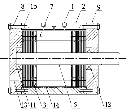
[0016] Referring to the accompanying drawings, the present invention provides a blisk-type boundary layer turbine, which includes a cylinder body 2, end covers 8 and 9 installed at both ends of the cylinder body 2, and also includes bearings 11 and 12 passing through the end cover and The rotating shaft 5 supported in the center of the cylinder, the rotating shaft 5 is installed with the working disc group 14, the blade 4 is installed between the adjacent working discs 3 in the working disc group 14, and the airflow direction at the inlet of the nozzle 1 is the same as that at the inlet of the blade 4. The included angle of the blade shape is 0 degree; the above-mentioned turbine working disk set 14 is provided with an outlet airflow passage 7, and the left end cover 8 is provided with a turbine airflow outlet hole 13.

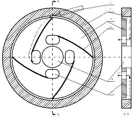
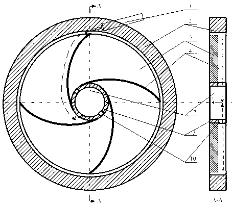
[0017] Refer below figure 2 , image 3 The operation process of the bladed disk boundary layer turbine provided by the present invention will be described i...


PUM


Abstract

The invention relates to a boundary layer turbine with a blade plate, which belongs to the field of energy and power and the like, is characterized by comprising a barrel (2), end covers (8, 9) arranged at two ends of the barrel, a rotating shaft (5) penetrating the end covers and supported at the center of the barrel (2) by bearings (11, 12), and a working plate group (14) arranged on the rotating shaft, wherein a blade (4) is arranged between every two adjacent working plates (3) in the working plate group (14) and divides an annular passage between the plates into a plurality of sector passages, an included angle between the inlet airflow direction of a nozzle (1) and a blade profile at the inlet of the blade (4) is 0 degree, the turbine working plate group is provided with an outlet airflow passage (7), and the end cover is provided with a turbine airflow outlet hole (13). The boundary layer turbine with the blade plate has the characteristics of being simple and compact in structure, high in efficiency, shake-resistant and wide in fluid application range, and being especially applicable to an organic Ranking cycle (ORC) generating system with small scale and low temperature.

Description

technical field [0001] The invention relates to a bladed disk-type boundary layer turbine, which belongs to the field of energy and power. Background technique [0002] The disc-type boundary layer turbine has the characteristics of simple structure, low machining requirements, low cost and wide range of fluid application. Flue gas from the combustion of unconventional fuels such as biomass. Since the annular channel formed by every two adjacent working disks in the disk-type boundary layer turbine working disk group has a self-cleaning function, it is also suitable for multi-phase fluids with particles. [0003] However, the current research on the disk boundary layer turbine is limited to the laboratory and has not been widely used. The main problems affecting the application of disk boundary layer turbines are their low efficiency and short life. Disc turbines that only rely on the frictional torque of the boundary layer to drive the rotating shaft to rotate to achieve...

Claims


Application Information

Patent Timeline
Patent Type & Authority Patents(China)
IPC IPC(8): F01D5/14F01D9/04
Inventor 岳晨韩东焦炜琦
Owner NANJING UNIV OF AERONAUTICS & ASTRONAUTICS
Why Eureka
Try Eureka