Supercharge Your Innovation With Domain-Expert AI Agents!

Making method of large-scale cavity foaming part molding die and die structure thereof

A molding die and manufacturing method technology, applied in the molding field of other foam plastics, can solve the problems of large processing volume of upper and lower dies, high processing cost, long processing cycle, etc., achieve small processing volume, reduce processing allowance, and improve processing efficiency Effect

Active Publication Date: 2012-10-10
HUBEI SANJIANG AEROSPACE WANFENG TECH DEV
View PDF0 Cites 0 Cited by
  • Summary
  • Abstract
  • Description
  • Claims
  • Application Information

AI Technical Summary

Problems solved by technology

[0002] Traditional foaming molds are generally made of aluminum sand castings or stainless steel as a whole. The upper and lower molds have a large amount of processing and a long processing cycle, especially for large foaming parts (width greater than 1200mm, height greater than 300mm) with relatively large For parts with large curved surfaces, the punch and die processing of the mold must rely on large-scale CNC machine tools, and the processing costs are very high; especially for enterprises that lack large-scale CNC processing equipment, it is difficult to produce such large-scale Molds are hard to do

Method used


Image

  • Making method of large-scale cavity foaming part molding die and die structure thereof
  • Making method of large-scale cavity foaming part molding die and die structure thereof
  • Making method of large-scale cavity foaming part molding die and die structure thereof

Examples


Embodiment Construction

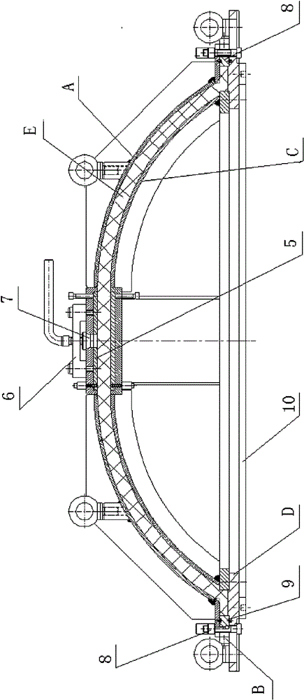
[0027] figure 1 It is a longitudinal sectional view of the large cavity foaming part molding die structure die of the present invention:

[0028] The structure of the large-cavity foamed part forming mold of the present invention includes an upper mold and a lower mold, the upper mold includes a concave mold body A and a chassis B, the lower mold includes a convex mold body C and a base D, and E is a large-cavity foamed part.

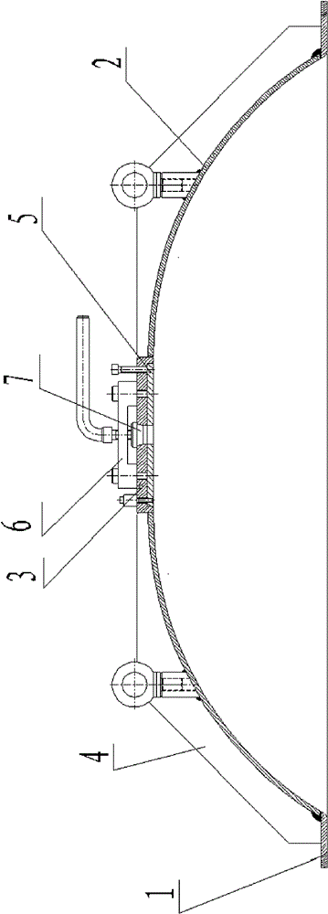
[0029] The inner side of the concave model body A has a groove, and the top plate 5 is placed in the groove, and the top plate 5 is connected to the top of the concave model body A by bolts; the top of the concave model body A is provided with a sprue, a sprue plug 7 and a movable pressure rod assembly 6. The pouring hole runs through the top of the concave model body A to the cavity, and the movable pressing rod assembly 6 is used to compress the pouring port plug 7 . The chassis B of the upper mold and the base D of the lower mold are connected by b...


PUM


Abstract

The invention provides a making method of a large-scale cavity foaming part molding die and a die structure thereof. The making method comprises the following steps of: making an upper die model body, a lower die model body and a chassis, wherein in the production of the upper die model body and the lower die model body, a cavity surface is disassembled into a small square at the top and four same isosceles curved-edge trapezoid arc surfaces by adopting the same splicing method, wherein each isosceles curved-edge trapezoid arc surface has the upper bottom d, the lower bottom L and the height S; making four same isosceles curved-edge trapezoid arc plates, a flange frame provided with an inner frame with the side length L and matched with the chassis B, and the small square with the side length d: first flatly placing the flange frame on a welding platform, placing a cavity mould in the middle of the flange frame, carrying out spot welding on abutted seams of the four isosceles curved-edge trapezoid arc plates, placing the small square with the side length d in a square hole formed by the upper bottoms of the four isosceles curved-edge trapezoid arc plates, carrying out spot weldingon each connecting part inside the small square, and overturning and fixing the small square subjected to spot welding and carrying out complete welding on the outer side of the small square; weldingreinforcing ribs on four outer side surfaces; reshaping, coping and polishing the molded surface of the cavity; connecting model bodies with the chassis to finish the production of an upper die.

Description

technical field [0001] The invention relates to a method for making a mold for forming a large-scale cavity foaming part and its mold structure, which is used for (hard) polyurethane foam to form a foaming mold for a large-scale foaming part. The invention is also applicable to other foaming plastics forming. It belongs to the technical field of mold making. Background technique [0002] Traditional foaming molds are generally made of aluminum sand castings or stainless steel as a whole. The upper and lower molds have a large amount of processing and a long processing cycle, especially for large foaming parts (width greater than 1200mm, height greater than 300mm) with relatively large For parts with large curved surfaces, the punch and die processing of the mold must rely on large-scale CNC machine tools, and the processing costs are very high; especially for enterprises that lack large-scale CNC processing equipment, it is difficult to produce such large-scale Molds are h...

Claims


Application Information

Patent Timeline
IPC IPC(8): B23P15/00B29C44/58
Inventor 邓平盛潘龙玉鲁兴武奂久平
Owner HUBEI SANJIANG AEROSPACE WANFENG TECH DEV
Features
  • R&D
  • Intellectual Property
  • Life Sciences
  • Materials
  • Tech Scout
  • Unparalleled Data Quality
  • Higher Quality Content
  • 60% Fewer Hallucinations
Learn More