Computer key adopting novel scissor structure

A technology of scissors and computer, which is applied in the direction of contact operating mechanism, electrical components, electric switches, etc., and can solve the problems of structural asymmetry, inability to realize automation, and low strength of scissors

Inactive Publication Date: 2011-09-07
江海波
View PDF3 Cites 6 Cited by
  • Summary
  • Abstract
  • Description
  • Claims
  • Application Information

AI Technical Summary

Problems solved by technology

No matter the application of notebook computer or desktop computer is inseparable from the computer keys, the existing notebook keys and some desktop computers such as the thin and light keys adopted by Apple computers have all adopted the structure of scissor feet, the existing scissor feet and key caps and The assembly structure of the key base plate is mostly: a pair of sliding side hooks and a pair of fixed card seats are respectively provided on the bottom surface of the key cap, and a pair of sliding side hooks and a pair of fixed card seats are respectively provided on the key base plate, and the scissors are assembled on the corresponding Between the key cap and the key bottom plate; such an assembly structure leads to the asymmetric structure of the inner frame and the outer frame of the scissors, which makes the strength of the scissors lower; when assembling, the left and right of the scissors must be checked manually And the corresponding assembly can only be done after the positive and negative directions, such a needle-threading operation wastes a lot of labor costs, and the accuracy is not high, it is easy to produce defective products, and it cannot be automated

Method used


Image

  • Computer key adopting novel scissor structure
  • Computer key adopting novel scissor structure
  • Computer key adopting novel scissor structure

Examples


Embodiment Construction

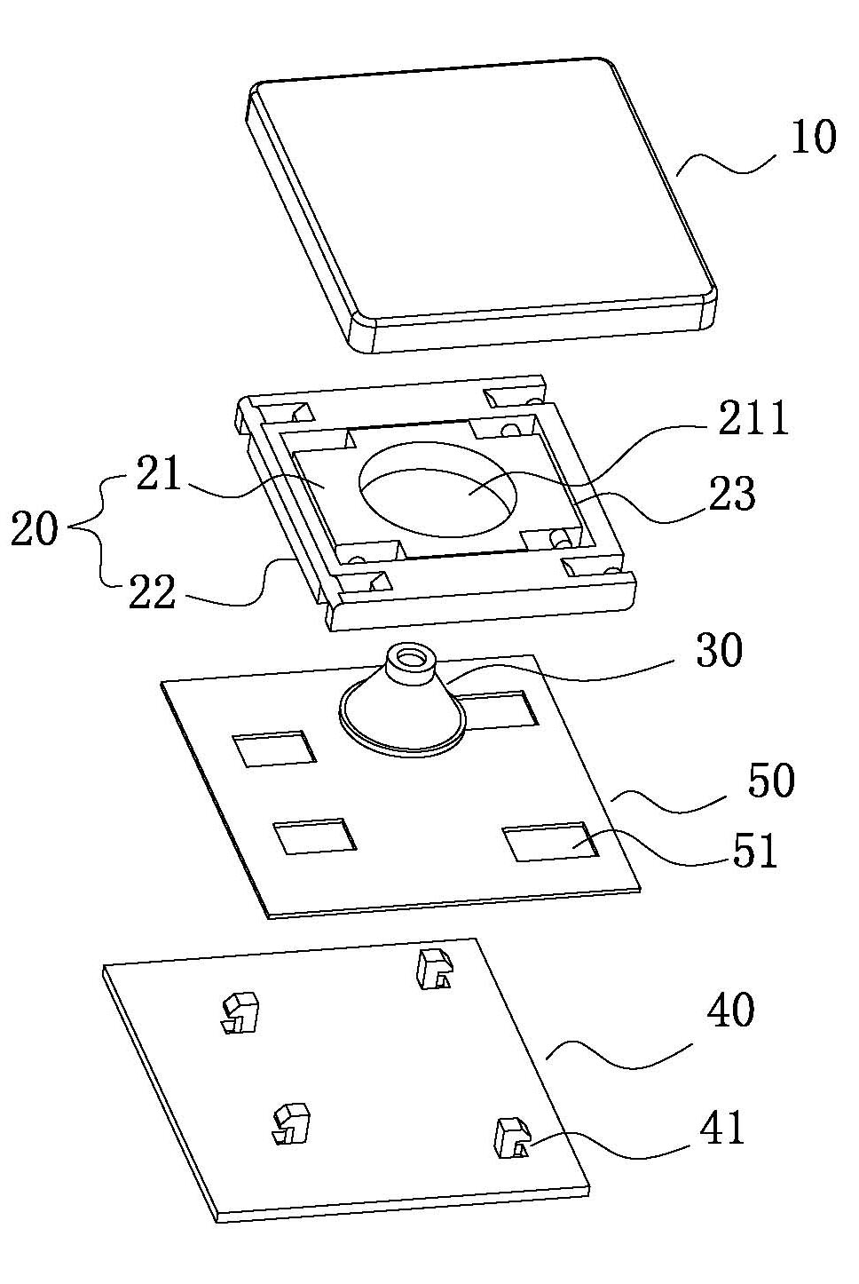
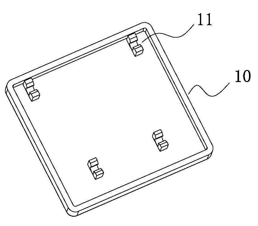
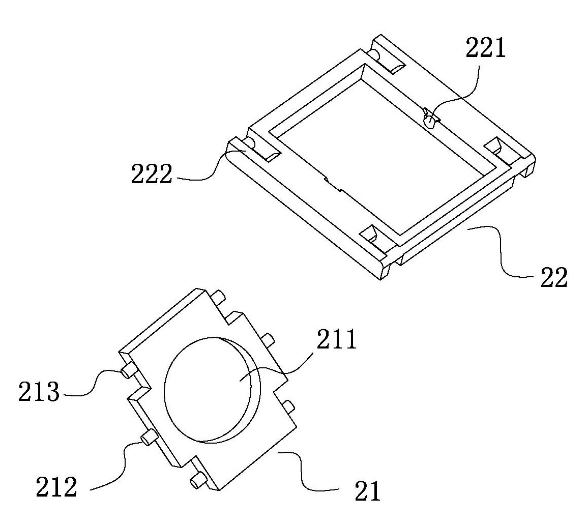
[0016] Such as Figure 1-3 As shown, a computer button adopting a novel scissor foot structure of the present invention includes: a key cap 10, a scissor foot 20, an elastic silicon gel 30, a key bottom plate 40 and a printed circuit film 50 covering the surface of the key bottom plate 40, The top of the elastic silicone body 30 passes through the through hole 211 of the scissors feet 20 and is set on the bottom surface of the key cap 10. The bottom of the elastic silicone body 30 is located on the key switch of the printed circuit film 50. The scissors feet 20 are hinged to each other The frame 21 and the outer frame 22 are composed of a rotating shaft 212 protruding from the center of the outer side of the two frames of the inner frame 21, and a shaft hole 221 corresponding to the rotating shaft 212 is provided at the center of the inner side of the two frames of the outer frame 22. 21 is hinged on the axis hole 221 of the outer frame 22 through the rotating shaft 212, and t...


PUM


Abstract

The invention relates to a computer key adopting a novel scissor structure. The computer key comprises a key cap, a scissor, elastic colloidal silica, a key bottom plate and a printed circuit film covering the surface of the key bottom plate, wherein a gap exists between the outer side surface of the border of an inner frame and the inner side surface of the border of an outer frame so that the inner frame can freely rotate 360 degrees relative to the outer frame; both the inner frame and outer frame are a frame of symmetrical structure; four corners of the inner frame are symmetrically provided with inner clamp pins of the same shape and size, and four corners of the outer frame are symmetrically provided with outer clamp pins of the same shape and size; the bottom surface of the key cap is provided with four fixing clamp seats of the same structure in trapezoidal distribution; and the key bottom plate is provided with four sliding side clamp hooks of the same structure in trapezoidal distribution. By adopting the structure, the computer key provided by the invention simplifies the production process, lowers the production cost, improves the assembly accuracy and automatic assembly efficiency, and is suitable for automatic production.

Description

technical field [0001] The invention relates to the technical field of computer keypads, in particular to a computer keypad with a novel scissors foot structure for notebook computers or desktop computers. Background technique [0002] With the development of the information industry, computers have been increasingly widely used. No matter the application of notebook computer or desktop computer is inseparable from the computer keys, the existing notebook keys and some desktop computers such as the thin and light keys adopted by Apple computers all adopt the structure of scissor feet, the existing scissor feet and key caps and The assembly structure of the key base plate is mostly: a pair of sliding side hooks and a pair of fixed card seats are respectively provided on the bottom surface of the key cap, and a pair of sliding side hooks and a pair of fixed card seats are respectively provided on the key base plate. Between the button cap and the bottom plate of the button; s...

Claims


Application Information

Patent Timeline
IPC IPC(8): H01H13/02H01H13/20H01H13/705H01H3/12
CPCH01H13/705H01H13/02H01H13/20H01H3/125
Inventor 江海波陈国安
Owner 江海波
Why Eureka
Try Eureka