Correlative oil leakage area imaging radar system of oil pipeline
An oil pipeline, imaging radar technology, applied in radio wave measurement systems, radio wave reflection/re-radiation, utilization of re-radiation, etc. rate increase effect
- Summary
- Abstract
- Description
- Claims
- Application Information
AI Technical Summary
Problems solved by technology
Method used
Image
Examples
Embodiment Construction
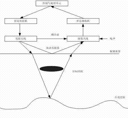
[0034] refer to figure 1 , including a radar signal transmitting circuit, a radar signal receiving circuit and a radar imaging processing unit, like a traditional radar system, transmit radar waves to a target or receive a reflected signal of a target through a radar antenna (transmitting antenna and receiving antenna), the buried In the detection and imaging of underground oil pipelines, the maximum detection depth is required to be 3.5 meters, that is, the distance difference between the target local oscillator and the target echo is about 7 meters, so the intermediate frequency of the received echo has a bandwidth of (at this time The dielectric constant of the earth is estimated by 9):
[0035]
[0036] In the above formula is the bandwidth of the received signal, is the modulation frequency of the transmitted chirp signal, is the speed of light, The dielectric constant of the earth, is the maximum operating distance.
[0037] This requires the transmitter to...
PUM
 Abstract
Description
Claims
Application Information
 - R&D Engineer
- R&D Manager
- IP Professional
- Industry Leading Data Capabilities
- Powerful AI technology
- Patent DNA Extraction
Browse by: Latest US Patents, China's latest patents, Technical Efficacy Thesaurus, Application Domain, Technology Topic, Popular Technical Reports.
© 2024 PatSnap. All rights reserved.Legal|Privacy policy|Modern Slavery Act Transparency Statement|Sitemap|About US| Contact US: help@patsnap.com


