
System and method for measuring diffusion flame frontal surface three-dimensional structure of motion fire source

A technology for spreading flames and three-dimensional structures, which is applied in measuring devices, fluid velocity measurement, velocity/acceleration/impact measurement, etc. It can solve the problem of the inability to obtain the three-dimensional spatial geometric characteristics of the flame front, the inability of the ignition source point to move, the running speed, and the trajectory Poor followability and other problems, to achieve the effect of flexible and convenient operation, realization of visualization and real-time, stable parameters

Inactive Publication Date: 2011-09-07
SOUTH CHINA UNIV OF TECH
View PDF5 Cites 14 Cited by
  • Summary
  • Abstract
  • Description
  • Claims
  • Application Information

AI Technical Summary

Problems solved by technology

The invention can overcome the defects that the ignition source point cannot be moved and its running speed cannot be controlled in the traditional flame front structure measurement process; it can also overcome the inability to obtain the three-dimensional spatial geometric characteristics and motion of the flame front with a single-lens CCD or single-lens high-speed photography Problems such as track and poor followability

Method used


Image

  • System and method for measuring diffusion flame frontal surface three-dimensional structure of motion fire source
  • System and method for measuring diffusion flame frontal surface three-dimensional structure of motion fire source
  • System and method for measuring diffusion flame frontal surface three-dimensional structure of motion fire source

Examples


Embodiment Construction

[0044] The specific embodiments of the present invention will be further described below in conjunction with the accompanying drawings, but the implementation and protection scope of the present invention are not limited thereto.

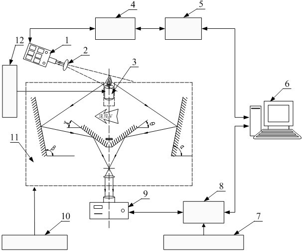
[0045] Such as figure 1 As shown, it is a structural schematic diagram of the three-dimensional structure measurement system of the moving fire source diffusion flame front in this embodiment. The measurement system includes a laser 1, a smooth lens 2, a diffusion burner 3, a synchronous controller 4, a stabilized voltage and lighting power supply 5, a computer 6, an acquisition control device 7, an image acquisition card 8, an image acquisition device 9, and an optical system adjustment Device 10 , imaging optical system 11 , speed control system 12 . The laser 1 can be a pulsed iridium-neodymium garnet laser 1 (Nd:Yag laser), and the Nd:Yag laser 1 is fixed on the floor through a support. The Nd:Yag laser 1 supplies the wide dynamic range laser...


PUM

PropertyMeasurementUnit
Thicknessaaaaaaaaaa

Abstract

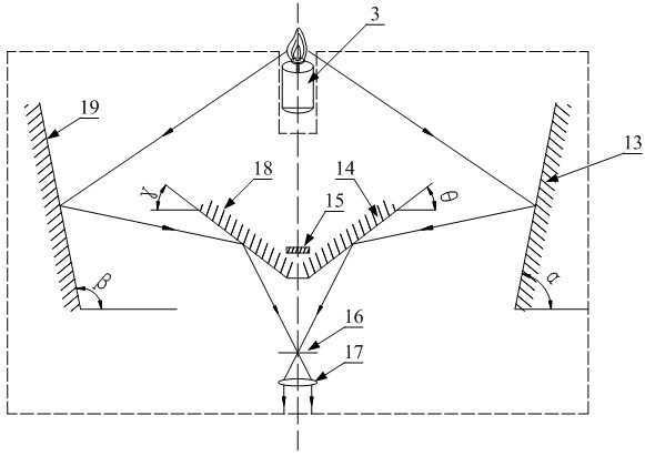
The invention discloses a system and method for measuring a diffusion flame frontal surface three-dimensional structure of a motion fire source. The system comprises a laser, a sheet mirror side lens, a diffusion combustor, a synchronous controller, a voltage-stabilizing and illuminating unit, a controller, an image acquisition card, an image acquisition device, an optical system regulation device, an image optical system and a speed control system, wherein the imaging optical system comprises a right primary reflection lens, a right secondary reflection lens, a light screen, a plane lens, a collimation lens, a left secondary reflection lens and a left primary reflection lens. The method can be used for regulating motion speed of the combustor through a speed control system and regulating diffusion flame so as to obtain the diffusion flame frontal surface of a motion fire source under various motion speeds and combustion strengths. Due to the adoption of the invention, images of the left side and the right side of the flame frontal surface are obtained on a CCD imaging element through the imaging optical system, non-contact measurement can be realized, and a three-dimensional structure of the high-precision flame frontal surface can be obtained through image reconstruction.

Description

technical field [0001] The invention relates to the technical field of flame front measurement, in particular to a system and method for measuring the three-dimensional structure of a moving fire source diffusion flame front. Background technique [0002] The fuel and oxidant are separated before combustion in the form of a flame called non-premixed flame (non-premixed flame). The non-premixed combustion flame is mainly carried out by mutual diffusion between fuel and oxidant, so it is also called diffusion flame. Diffusion flame is a more common form of flame in nature and practical applications, such as the flame of candles, the flame produced by direct combustion of solid fuels such as coal and wood, and the combustion of direct injection fuel in rocket engines, aircraft engines, gas turbines and diesel engines. All flames are diffuse flames. Among them, the fire caused by the direct combustion of liquid or solid fuel is the most common diffuse combustion in real life t...

Claims


Application Information

Patent Timeline
IPC IPC(8): G01B11/24G01P5/22
Inventor 龙新峰楼波
Owner SOUTH CHINA UNIV OF TECH
Learn More