
Lens driving device, camera, and camera-equipped cellular phone

A lens driving device and lens technology, applied to cameras, electromechanical devices, focusing devices, etc., can solve problems such as difficulty in use, time-consuming spring attachment, etc., and achieve the effect of easy selection and design

Active Publication Date: 2013-10-23
NEW SHICOH MOTOR CO LTD
View PDF4 Cites 0 Cited by
  • Summary
  • Abstract
  • Description
  • Claims
  • Application Information

AI Technical Summary

Problems solved by technology

However, since the terminal is extremely small, it is difficult to use, and at the same time, it is very labor-intensive to connect (welding, etc.) to the spring.

Method used


Image

  • Lens driving device, camera, and camera-equipped cellular phone
  • Lens driving device, camera, and camera-equipped cellular phone
  • Lens driving device, camera, and camera-equipped cellular phone

Examples


Embodiment Construction

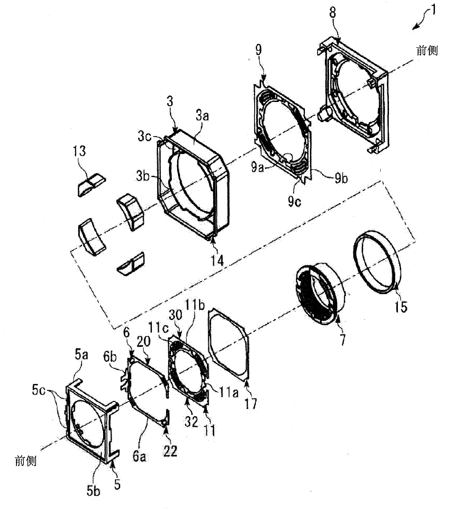
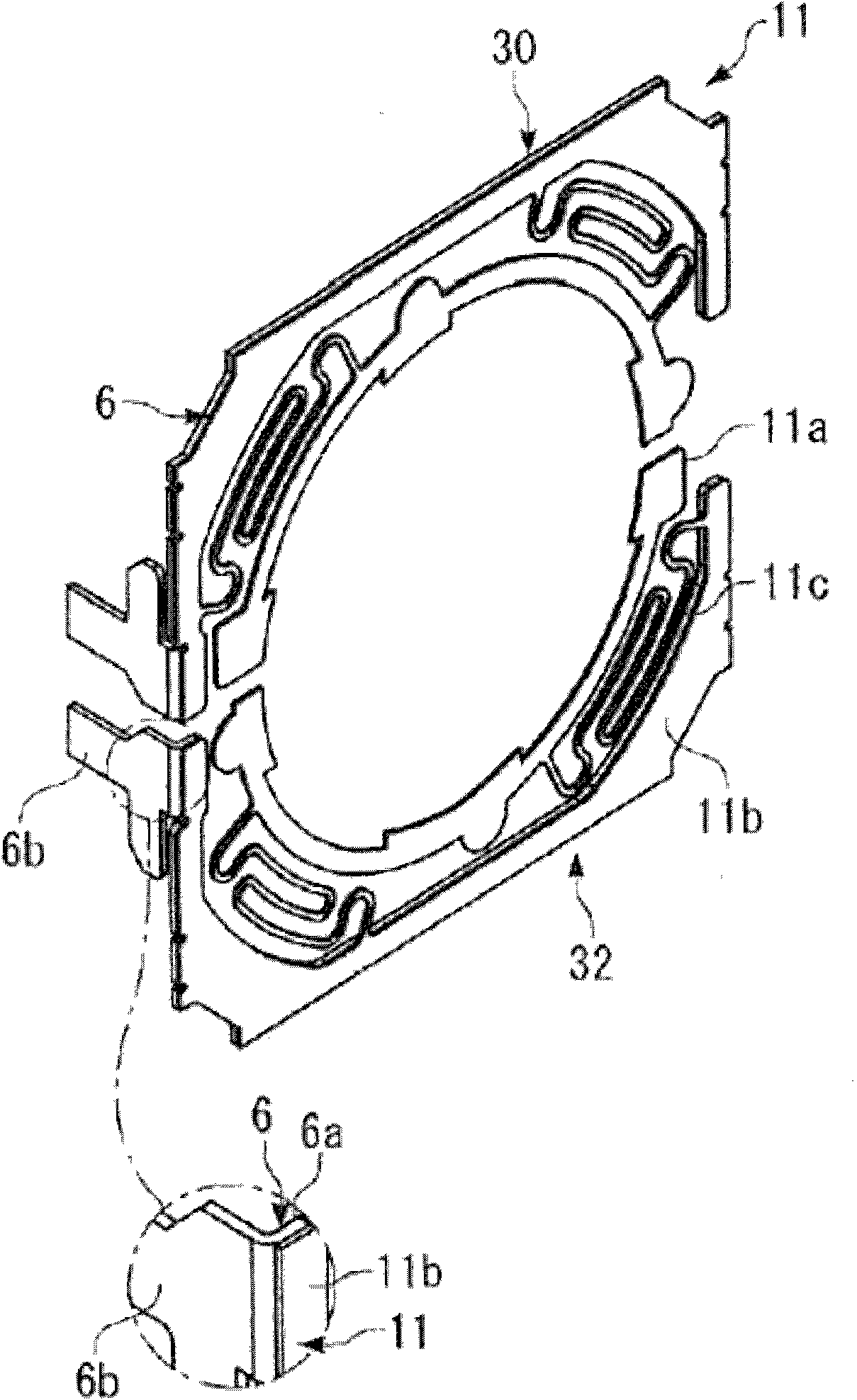
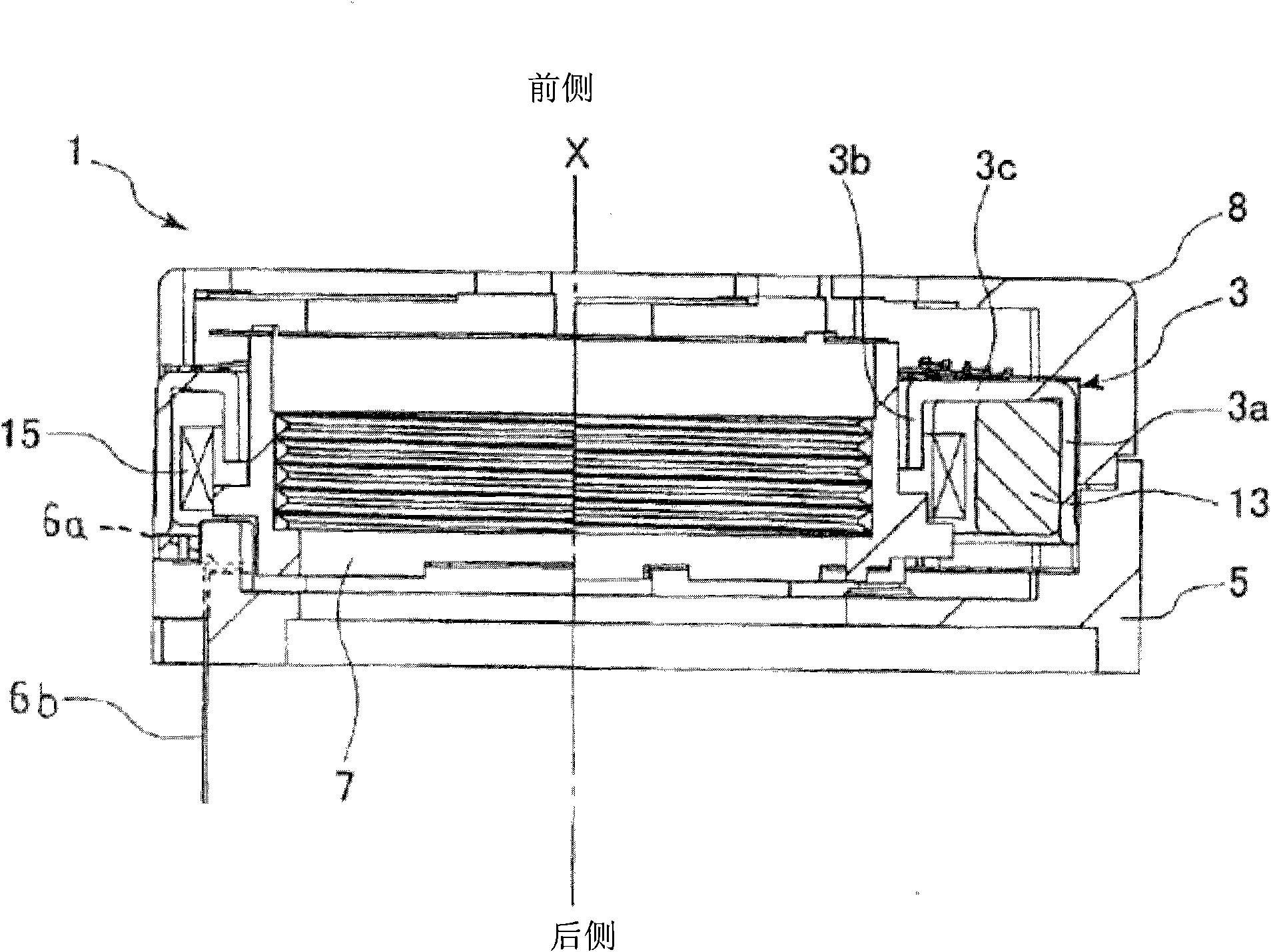
[0028] Hereinafter, embodiments of the present invention will be described with reference to the drawings. The lens driving device 1 related to the first embodiment is a lens driving device of an auto-focus camera function machine assembled in a mobile phone. The lens driver such as figure 1 and image 3 As shown, it has an annular ring mouth 3, a lens support body 7, a front side spring 9, a rear side spring (spring) 11, a base 5 (frame) arranged on the rear side of the ring mouth 3, and a frame 8 on the front side of the A coil 15 is fixed to the outer periphery of the lens support 7 , an insulator (spacer) 17 is disposed between the ring 3 and the rear spring 11 , and a terminal member 6 is disposed between the rear spring 11 and the base 5 . The lens driving device 1 is about 10mm in width and 3.5mm in height, which is a very small structure.

[0029] Seen from the front side, the ring mouth 3 is quadrangular in plan view of its outer periphery, and circular in plan vi...


PUM


Abstract

A lens driving device 1 is provided, in which a spring 11 includes an outer ring portion 11b that is fixed to a body 5, an inner ring portion 11a that is fixed to a lens support 7, and an arm portion 11c that connects the outer ring portion 11b and the inner ring portion 11a, and the lens support 7 is moved in an optical axis direction of a lens by way of an electromagnetic force that is generated by applying electric current to a coil 15 from a terminal member 6, the terminal member 6 including a superimposed portion 6a that is superimposed on the outer ring portion of 11b of the spring 11, and a power supply terminal 6b that protrudes from the superimposed portion 6a, and the terminal member 6 disposing the superimposed portion 6a between the outer ring portion 11b of the spring and the body 5.

Description

technical field [0001] The present invention relates to a lens drive device for autofocus used in a compact camera, a camera-function machine equipped with the lens drive device, and a mobile phone with a camera function. Background technique [0002] The prior art related to this application includes: Patent Document 1, Publication No. JP2007-143210; Patent Document 2, Publication No. JP2009-14890. [0003] In Patent Document 1, it is disclosed that a spring set between the frame and the lens support supports the lens support to move smoothly along the optical axis relative to the frame. The spring is electrically connected to the coil, the terminal is arranged on the spring, and the coil is energized after the spring is inserted. [0004] The spring in Patent Document 1 is integrated with the power supply terminal protruding from the frame. In addition, in Patent Document 2, in the same structure as the lens driving device described in Patent Document 1, it is disclosed ...

Claims


Application Information

Patent Timeline
Patent Type & Authority Patents(China)
IPC IPC(8): G02B7/09G03B13/36H02K33/18H04M1/02
CPCG02B7/023G02B13/001G02B7/022G02B7/08H04N5/2257H04N23/57
Inventor 白木学外山宏慈
Owner NEW SHICOH MOTOR CO LTD
Learn More