Monitoring device and monitoring method for lift wall deformation of ship lock

A deformation monitoring and sluice chamber wall technology, which is used in measuring devices, surveying and navigation, measuring inclination, etc., can solve the problem of not considering mutual use, lack of coherence of monitoring data, and inability to fully monitor the settlement of sluice chamber walls, etc. question

Inactive Publication Date: 2012-06-27
HOHAI UNIV
View PDF0 Cites 0 Cited by
  • Summary
  • Abstract
  • Description
  • Claims
  • Application Information

AI Technical Summary

Problems solved by technology

[0006] 1. Due to reasons such as excavation and backfilling during the construction period and the segmental construction of each part of the lock chamber wall, the monitoring points set at the beginning of the construction are forced to be abandoned after a period of use, and the monitoring points are often forced to be reset or the path of the monitoring route. Lack of consistency in monitoring data
[0007] 2. The monitoring points during the construction period cannot continue to be used after the operation period due to reasons such as water injection in the lock chamber and soil filling behind the lock chamber wall, making the monitoring data during the construction period and the operation period relatively independent
[0008] 3. Although the leveling method is currently used for the settlement of the lock chamber wall, the arrangement of the measuring points in each part is mostly random, without considering the mutual use, and the settlement of the lock chamber wall cannot be fully monitored
[0009] 4. For the monitoring of the displacement and local deformation of the lock chamber wall, there is no relatively fixed device and method at home and abroad to systematically monitor the deformation of the lock chamber wall

Method used


Image

  • Monitoring device and monitoring method for lift wall deformation of ship lock
  • Monitoring device and monitoring method for lift wall deformation of ship lock
  • Monitoring device and monitoring method for lift wall deformation of ship lock

Examples


Embodiment Construction

[0030] The technical scheme of the present invention is described in detail below in conjunction with accompanying drawing:

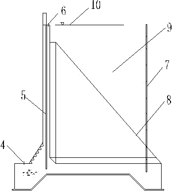
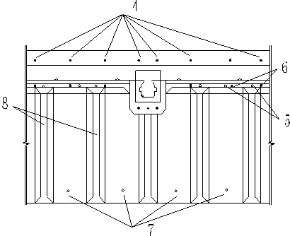
[0031] Such as figure 1 , figure 2 As shown, the ship lock chamber wall deformation monitoring device of the present invention comprises,

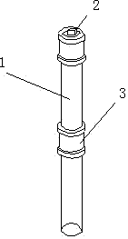
[0032] A preset measurement reference point 11 at a certain distance from one side of the ship lock; a plurality of settlement observation points 4 and 6 respectively arranged on the front toe floor of the ship lock chamber wall and the top of the lock chamber wall, each of which is 6 in number, and the ship lock chamber The six settlement observation points 4 on the surface of the toe floor in front of the wall and the six settlement observation points 6 on the top of the lock chamber wall are symmetrically distributed in the vertical direction; they are vertically buried in the concrete between the two buttresses 8 of the rear toe floor of the lock chamber wall 4 metal pipe strings 7 inside, the metal pipe stri...


PUM


Abstract

The invention discloses a monitoring device for lift wall deformation of a ship lock and belongs to the technical field of civil engineering construction. The monitoring device comprises a preset datum mark, a plurality of settlement observation points, a plurality of metal tubular columns, a plurality of inclinometers, and a plurality of displacement observation points, wherein the settlement observation points are in one-to-one symmetrical distribution along the vertical direction and are arranged on a front toe baseboard of the lift wall of ship lock and the top end of the lift wall; the metal tubular columns which comprise a plurality of same metal tubes are vertically embedded in a back toe baseboard of the lift wall; the inclinometers are vertically embedded in the lift wall concrete and the upper ends of the inclinometers are exposed out of the top end of the lift wall; the inclinometers are formed by a plurality of same flexible tubes which are connected in turn following the increasing of the construction height of the lift wall; and the displacement observation points are arranged on the top end of the lift wall. The invention also discloses a method for monitoring the lift wall deformation of a ship lock by using the device. By using the method and device provided by the invention, the defect that the traditional construction monitoring and operation period monitoring are mutually separated is avoided, the long-term, systematic and precise monitoring for the lift wall of a ship lock is realized, and the engineering use value is higher.

Description

technical field [0001] The invention relates to a method for monitoring deformation of civil structures, in particular to a device and method for monitoring deformation of a lock chamber wall of a ship lock, belonging to the technical field of civil engineering construction. Background technique [0002] The lock chamber wall of the ship lock is an important part of the ship lock project, and its construction quality is directly related to the success or failure of the entire ship lock project. The height of the lock chamber wall is generally at least ten meters. The wall itself has a certain deflection. Improper construction will cause local bending deformation. Secondly, the pressure on the front and rear toes of the wall foundation is not uniform, resulting in the difference in the compression of the foundation soil. In addition, the length of the lock chamber of the ship lock is long, and the differences in the soil pressure behind the wall, base soil layer, and construc...

Claims


Application Information

Patent Timeline
Patent Type & Authority Patents(China)
IPC IPC(8): G01C5/00G01C9/00
Inventor 庄宁何良德郑金海陈达王新峰
Owner HOHAI UNIV
Why Eureka
Try Eureka