Surface layer template connecting structure of cast-in-place concrete sloping roof

A technology for connecting structures and sloping roofs, applied in the direction of roof covering, connecting parts of formwork/formwork/work frame, roof, etc. Section size and appearance quality, ensure compactness requirements, and solve the effect of structural leakage

Inactive Publication Date: 2011-08-31
CHINA CONSTR SEVENTH ENG BUREAU THE SECOND CO LTD
View PDF3 Cites 7 Cited by
  • Summary
  • Abstract
  • Description
  • Claims
  • Application Information

AI Technical Summary

Problems solved by technology

However, due to the difficulty in construction of the cast-in-place sloping roof structure, often due to improper selection of construction technology, it is easy to cause the concrete to be poured and tamped thick enough or not dense enough to leave hidden dangers, resulting in roof leakage in the future
[0003] In the construction of traditional cast-in-place concrete sloping roofs and upsloping roofs (usually referring to sloping roofs with a slope between 30°-60°), the formwork on the bottom surface of the slope is often used or a layer of steel wire mesh is added to the reinforcement surface for pouring and compaction. However, due to the steepness of the slope, the concrete can only be naturally formed on the slope without restraint. The concrete is often slipped and segregated during the concrete vibration process. It is difficult to control the compactness of the concrete and the construction quality is difficult to achieve the expected effect. Leave hidden dangers of seepage and leakage to concrete structure construction

Method used


Image

  • Surface layer template connecting structure of cast-in-place concrete sloping roof
  • Surface layer template connecting structure of cast-in-place concrete sloping roof
  • Surface layer template connecting structure of cast-in-place concrete sloping roof

Examples


Embodiment Construction

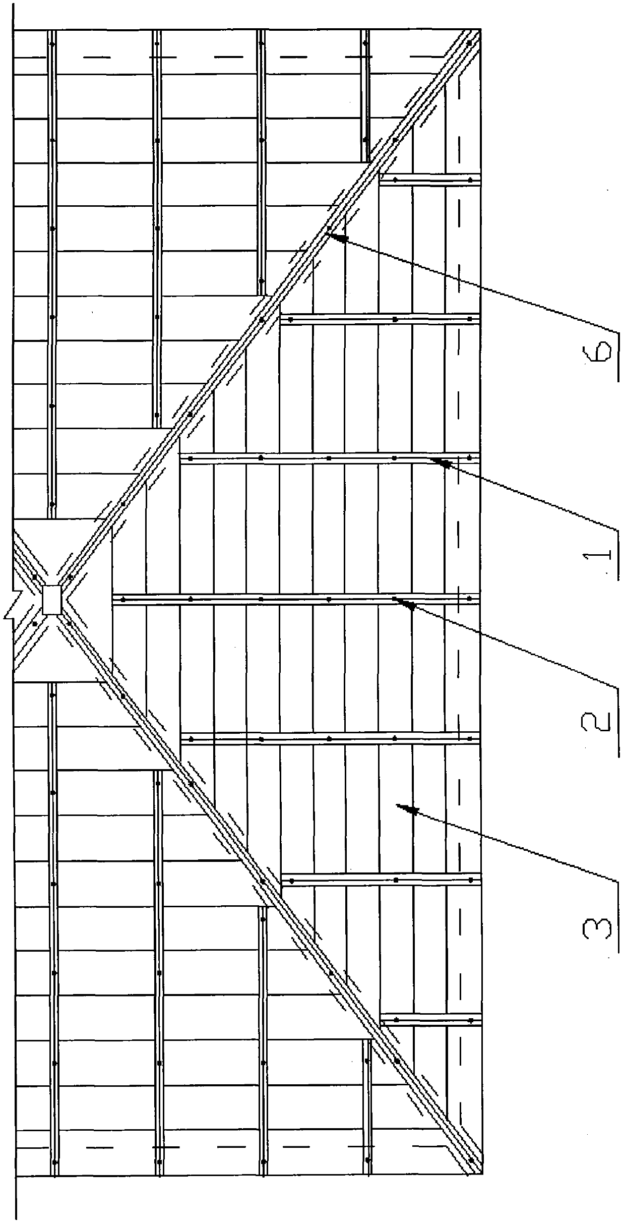
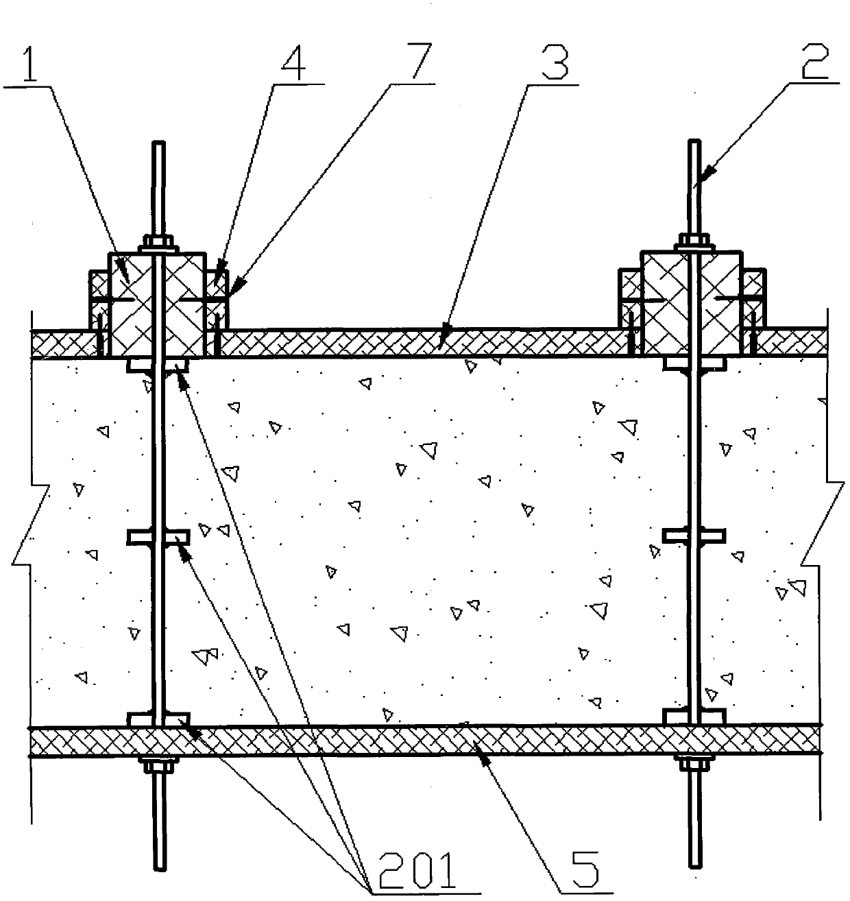
[0014] exist figure 1 Among them, a cast-in-place concrete sloping roof surface formwork connection structure is used to build a compact sloping roof structure with a slope of 45°, including a bottom formwork 5, a surface formwork 3, water-stop bolts 2, and a plurality of vertical keels 1 and a plurality of side keels 4, the bottom formwork 5 is located on the bottom surface, the vertical keels 1 are distributed parallel to each other above the bottom formwork 5, and the length direction of the vertical keels 1 is consistent with the direction from the bottom of the slope to the top of the slope.

[0015] Such as figure 2 As shown, the water-stop bolt 2 is made by welding three pieces of water-stop sheets 201 in the middle section of the pull bolts, wherein the welding positions of the water-stop sheets at both ends of the bolts just match the pouring thickness of the concrete. The lower end of the water stop bolt 2 passes through the bottom template and is fixedly connected...


PUM


Abstract

The invention discloses a surface layer template connecting structure of a cast-in-place concrete sloping roof, which a compact sloping roof structure suitable for building a slope between 30 degrees and 60 degrees. The surface layer template connecting structure of the cast-in-place concrete sloping roof comprises a bottom layer template, a surface layer template, a water stopping bolt, a plurality of vertical keels and a plurality of side keels, wherein the bottom layer template is positioned on a bottom surface; the vertical keels are distributed in parallel above the bottom layer template; length directions of the vertical keels are consistent with the direction from a slope bottom to a slope top; one end of the water stopping bolt is connected with the bottom layer template while the other end of the water stopping bolt is connected with the vertical keels; side surfaces of the side keels are connected with side surfaces of the vertical keels; the surface layer template is a stripped wood plate with length adaptive to a distance between the adjacent vertical keels; and two ends of the surface layer template are connected with the side keels. In the invention, because the surface layer template connecting structure located by the vertical keels and limited by the water stopping bolt is adopted, the thickness of the sloping roof structure is controlled, the foundation is laid for mounting the surface layer template, a compactness requirement on the concrete structure is assured, and the construction difficulty of the structure leakage is fundamentally solved.

Description

[technical field] [0001] The invention relates to a building formwork, in particular to a formwork connection structure of a cast-in-place concrete slope roof surface layer suitable for building a compact slope roof structure with a slope between 30° and 60°. [Background technique] [0002] At present, there are more and more buildings with various sloping roof structures, especially the application of cast-in-place concrete sloping roof structures in the construction of houses and structures is becoming more and more extensive. Especially in developed coastal cities, there are many novel, diverse and artistic forms of cast-in-place concrete sloping roof structures in architectural design. However, due to the difficulty in construction of the cast-in-situ sloping roof structure, often due to improper selection of construction technology, it is easy to cause insufficient thickness or compactness of the concrete poured and tamped, leaving hidden dangers, resulting in roof leak...

Claims


Application Information

Patent Timeline
IPC IPC(8): E04G11/36E04G17/00E04D7/00
Inventor 肖必建王伟民周爱明游兴荣刘光星曲鸿飞
Owner CHINA CONSTR SEVENTH ENG BUREAU THE SECOND CO LTD
Why Eureka
Try Eureka