Image blur correction device, imaging lens unit, and camera unit

A shake correction and lens technology, applied in cameras, projection devices, printing devices, etc., can solve problems such as thermal damage or damage, miniaturization of movable members (narrow width, transmission to movable member 2 or lens G, etc.)

Inactive Publication Date: 2011-08-24
COPAL CO LTD
View PDF9 Cites 13 Cited by
  • Summary
  • Abstract
  • Description
  • Claims
  • Application Information

AI Technical Summary

Problems solved by technology

[0008] However, in order to ensure that the welded portion 4b is formed on the front surface of the movable member 2, it is difficult to downsize the movable member (narrow width), etc.
In addition, because the welding portion 4b is close to the lens G, the heat of the soldering iron may be transferred to the movable member 2 or the lens G during the welding operation, and the movable member 2 or the lens G may be thermally damaged or damaged.

Method used


Image

  • Image blur correction device, imaging lens unit, and camera unit
  • Image blur correction device, imaging lens unit, and camera unit
  • Image blur correction device, imaging lens unit, and camera unit

Examples


Embodiment Construction

[0160] Hereinafter, preferred embodiments of the present invention will be described with reference to the drawings.

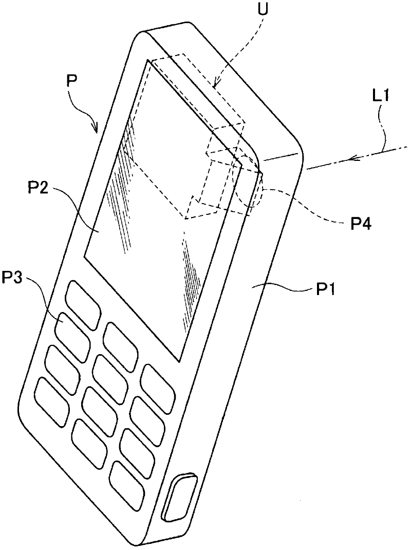
[0161] Such as figure 1 As shown, the camera unit U incorporating the image shake correction device is mounted on a flat and small portable information terminal P. The portable information terminal P has a frame P1 formed in a substantially rectangular and flat outline, a display portion P2 such as a liquid crystal panel that displays various information and is arranged on the surface of the frame P1, and operation buttons P3, which are formed on the display portion P2. The photographing window P4 etc. on the opposite surface. And like figure 1 As shown, the camera unit U is housed in the housing P1 so as to extend in a direction perpendicular to the optical axis L1 of the subject light entering from the photographing window P4.

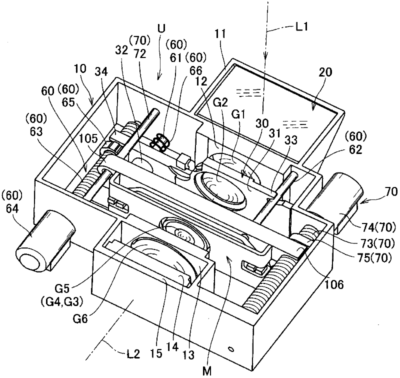
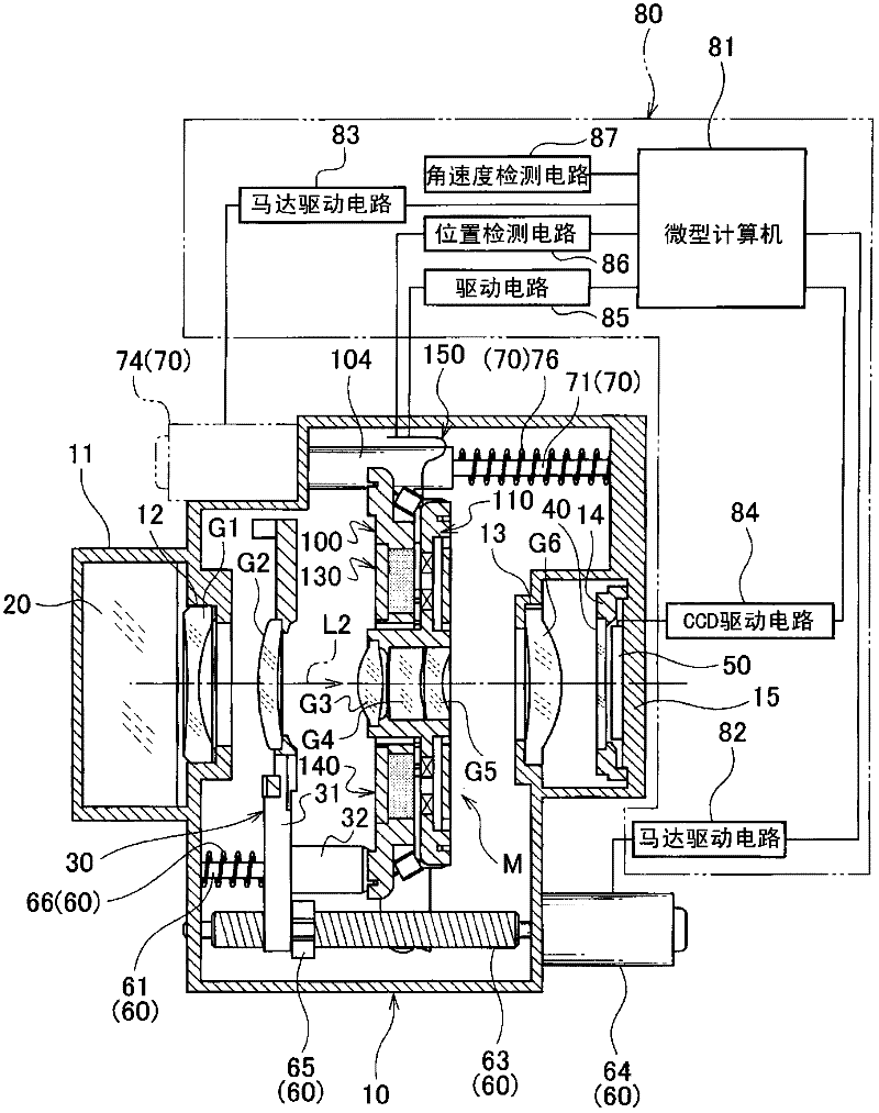
[0162] Such as figure 2 with image 3 As shown, the camera unit U has a unit box 10, a prism 20, a lens G1, a first movable lens gro...


PUM


Abstract

An image blur correction device comprises: a flat plate-like base (100) having an opening section (101) open in an optical axis direction; a flat plate-like movable holding member (110) for holding a lens and supported so as to be movable within a plane perpendicular to the optical axis of the lens; a first drive mechanism (130) including a first magnet and a first coil to drive the movable holding member in a first direction perpendicular to the optical axis; a second drive mechanism (140) including a second magnet and a second coil to drive the movable holding member in a second direction perpendicular to the optical axis; and detecting means (170, 180) for detecting the position of the movable holding member. The movable holding member is movably supported located adjacent to a base. The first drive mechanism and the second drive mechanism are arranged at positions line-symmetrical with respect to a first straight line (S1) perpendicular to the optical axis of the lens. The configuration allows the device to be reduced in size and thickness and can highly accurately correct a shift of the optical axis of the lens due to hand shaking.

Description

Technical field [0001] The present invention relates to an image blur correction device (image blur correction device) mounted on a lens barrel or shutter unit of a digital camera, an imaging lens unit and a camera unit having the image blur correction device, and more particularly to an image blur correction device mounted on a portable telephone. Small and thin image shake correction devices, imaging lens units, and camera units used in camera units on portable information terminals. Background technique [0002] As a conventional image shake correction device, the following structure is known, that is, it has: a substantially rectangular base with an opening in the center; a first guide shaft provided on the front surface of the base; and a first movable member , Which can be supported to reciprocate freely along the first guide shaft; the second guide shaft, which is oriented in a direction at 90 degrees to the first guide shaft, and is arranged on the front surface of the fi...

Claims


Application Information

Patent Timeline
Patent Type & Authority Applications(China)
IPC IPC(8): G03B5/00H04N5/232
CPCG03B17/04G03B17/02H04N5/2254H04M1/0264G03B5/00H04N5/23248H04N5/23258H04N23/55H04N23/68H04N23/6812
Inventor 渡部博之
Owner COPAL CO LTD
Why Eureka
Try Eureka