Eureka AIR delivers breakthrough ideas for toughest innovation challenges, trusted by R&D personnel around the world.

Forming method of no-material-head shaft piece by cross wedge rolling

A headless, cross-wedge rolling technology, which is applied in metal rolling and other directions, can solve the problems of reducing material utilization and achieve the effects of improving material utilization, good surface quality, and reducing production costs

Active Publication Date: 2011-08-24
山东泰金精锻股份有限公司
View PDF5 Cites 11 Cited by
  • Summary
  • Abstract
  • Description
  • Claims
  • Application Information

AI Technical Summary

Problems solved by technology

Although the material utilization rate of the cross-wedge rolling process is much higher than that of the forging and cutting processes, since the cross-wedge rolling process is a deformation process in which the metal is radially pressed and axially extended, the surface layer when rolling the end size The axial flow of metal is faster than that of the metal in the core, which causes a larger concave center at the end of the rolled piece, resulting in the formation of material heads in the rolled-formed parts, which need to be removed by cutting, which reduces the utilization of materials to a certain extent rate, the current material utilization rate of cross wedge rolling is generally below 85%

Method used


Image

  • Forming method of no-material-head shaft piece by cross wedge rolling
  • Forming method of no-material-head shaft piece by cross wedge rolling
  • Forming method of no-material-head shaft piece by cross wedge rolling

Examples


Embodiment Construction

[0015] The present invention will be further described in detail below in conjunction with the accompanying drawings and embodiments.

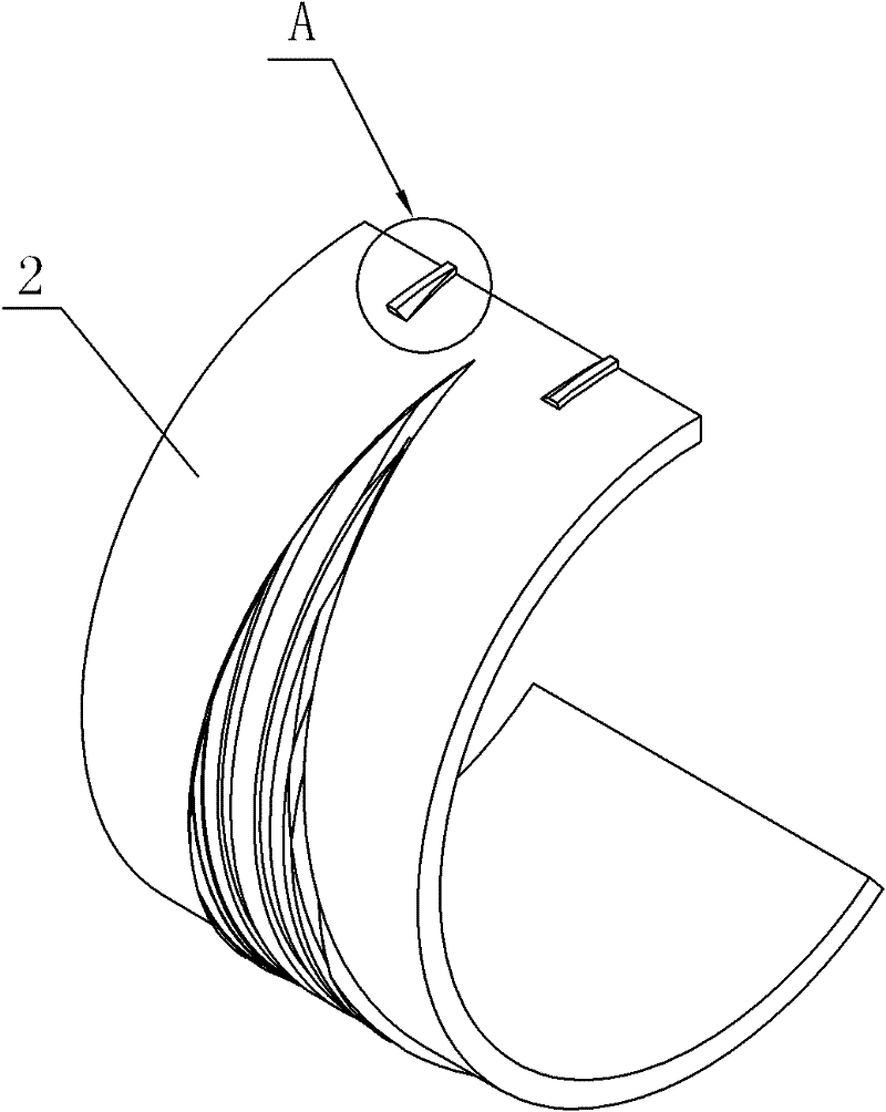
[0016] As shown in the figure, take a cylindrical blank, and use the mold shown in the attached figure to roll it into an output shaft in the form of one out of two. The specific process is as follows:

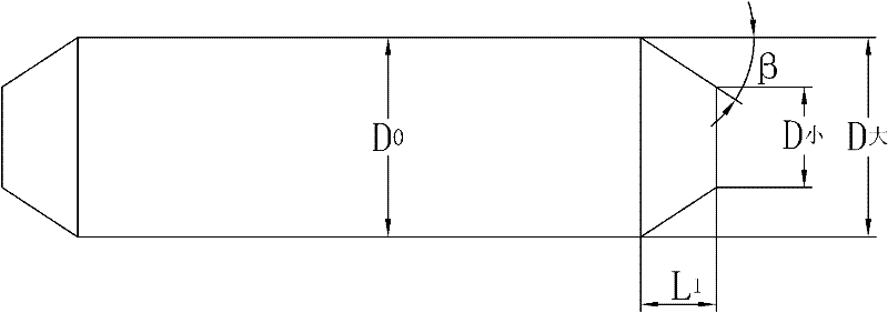
[0017] First design the outer diameter of the mold to be 800mm, and the forming angle of the mold to be 32 0 , widening angle is 8.5 0 , and then heat the cylindrical blank 1 to be rolled to 1200°C, and then send the blank 1 into the rolling die 2 through the axial feeding device on the cross wedge rolling mill for rolling. Part I of the mold 2 rolls both ends of the blank 1 into a linear truncated cone shape with the big end facing inward and the small end facing outward (such as figure 1 shown), and make the large head diameter of the linear frustum D 大 with the original diameter D of blank 1 0 Equal, the diameter of the small head of th...


PUM


Abstract

The invention discloses a forming method of a no-material-head shaft piece by cross wedge rolling. The forming method is characterized in that firstly the two ends of a blank are rolled into a linear frustum shape with an inward large head and an outward small head, simultaneously the whole length of the blank keep constant, then the blank with the two ends shaped like the linear frustum is rolled in the mold from the central section of the blank to the two ends of the blank according to the conventional cross wedge rolling method, and the no-material-head shaft piece meeting the requirementsis obtained. The forming method has the advantages that as the two ends of the blank are rolled into the linear frustum shape with the inward large head and the outward small head firstly in the rolling, consistent flowing between surface metal and core metal of a rolled piece in the following rolling process is guaranteed, the end part of the rolled piece generates a concave core, so that the rolled piece does not generate material heads, the material utilization rate is improved, the production cost is reduced, and the surface quality of the rolled shaft piece is good. In the forming method, the material utilization rate can be improved by more than 95%.

Description

technical field [0001] The invention relates to a plastic forming technology for shaft parts, in particular to a cross wedge rolling forming method for shaft parts without material heads. Background technique [0002] Cross wedge rolling is a new process for one-time forming of shaft parts. It has the advantages of high efficiency and material saving, and has been widely used at home and abroad. However, with the continuous promotion and application of cross wedge rolling technology, the requirements for cross wedge rolling technology are getting higher and higher. How to further improve the utilization rate of materials is a key factor to promote the promotion of cross wedge rolling technology. Although the material utilization rate of the cross-wedge rolling process is much higher than that of the forging and cutting processes, since the cross-wedge rolling process is a deformation process of metal radial compression and axial extension, the surface layer of the rolling en...

Claims


Application Information

Patent Timeline
Patent Type & Authority Applications(China)
IPC IPC(8): B21H1/00
Inventor 束学道孙宝寿黄海波梁冬泰肖旻魏新红漆良涛
Owner 山东泰金精锻股份有限公司
Why Eureka
Eureka Blog
Learn More