
Method for three-dimensionally rendering scene, graphic image treatment device, equipment and system

A processing device, graphic image technology, applied in the direction of stereo system, image data processing, image communication, etc., can solve the problem of the stereo effect of the viewer, achieve a good stereo effect and ensure the effect of comfort

Active Publication Date: 2011-08-17
SUPERD CO LTD
View PDF5 Cites 17 Cited by
  • Summary
  • Abstract
  • Description
  • Claims
  • Application Information

AI Technical Summary

Problems solved by technology

When the existing technology performs stereoscopic rendering on the scene, most of them are fixed L sep , and Z con Set in the middle of the scene, this can only guarantee the stereoscopic effect, but it cannot bring the viewer the most realistic stereoscopic effect

Method used


Image

  • Method for three-dimensionally rendering scene, graphic image treatment device, equipment and system
  • Method for three-dimensionally rendering scene, graphic image treatment device, equipment and system
  • Method for three-dimensionally rendering scene, graphic image treatment device, equipment and system

Examples


no. 1 example

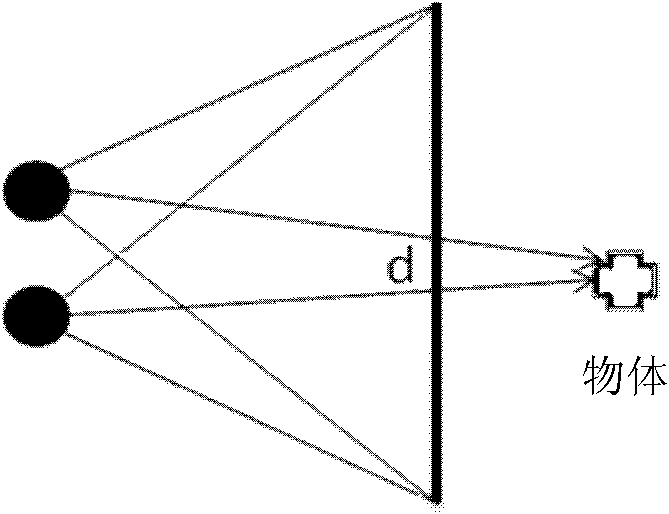
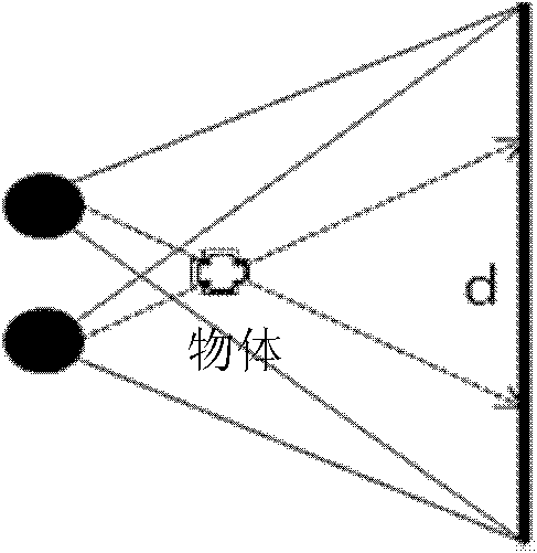
[0077] In this embodiment, when performing stereoscopic rendering on a scene composed of multiple objects, according to the characteristics of the scale of the scene and the distance between the camera and the scene, the depth of the zero-parallax plane of the first camera and the second camera is adjusted to obtain an ideal stereoscopic display Effect.

[0078] When people observe a small scene at close range, they will focus on an object and hope to see more details. Therefore, in stereoscopic display, if the object in the scene is made to protrude more, it will appear more real. Such as Figure 3a For example, when observing a small scene composed of a few objects at close range, you want the objects in front to protrude more. When people observe a large scene from a long distance, they want to get a more panoramic experience, so if the objects in the scene are recessed more during stereoscopic display, it can bring a stronger sense of three-dimensional depth. When observ...

no. 2 example

[0119] In the first embodiment, the distance L between the first camera and the second camera during rendering sep It can be processed in the manner of the prior art. This embodiment, on the basis of the first embodiment, adopts the determined distance L described below sep Methods.

[0120]The distance between human eyes is generally about 65mm, so the positive and negative parallax of the object in the first view and the second view should not be too large, otherwise it will cause eye fatigue. The positive and negative parallax of the object in the first view and the second view is related to the distance between the first camera and the second camera, the depth of the zero parallax surface and the depth of the object. Camera spacing is limited.

[0121] Please refer to Figure 8a , shows the disparity D of the pixel with the maximum depth in the first view and the second view in the scene to be rendered 1 ,D 1 >0, the zero parallax planes of the first camera and the s...


PUM


Abstract

The invention relates to a method for three-dimensionally rendering scene, a graphic image treatment device, equipment and system; the method comprises the following steps of: calculating the depth parameter related to the distance of the scene to be rendered between the scene and the camera and the scene scale parameter of the scene to be rendered; confirming the zero parallax surface depths of the first camera and the second camera according to the depth parameter related to the distance of the scene to be rendered between the scene and the camera and the scene scale parameter; rendering the scene to be rendered by using the first and the second cameras based on the confirmed zero parallax surface depths. Correspondingly, the graphic image treatment device comprises a scene analyzing module, a parameter confirming module and a three-dimensional rendering module; the graphic image treatment device can be used in mobile terminal, computer system and image obtaining equipment. Through the invention, the three-dimensionally rendered image has better three-dimensional display effect.

Description

technical field [0001] The present invention relates to a graphics processing technology, in particular to a method for stereo rendering of a scene, a graphics and image processing device and equipment, and a system. Background technique [0002] When the eyeball of the human eye looks at an object, it will first find a point of interest, so that the two eyeballs will converge (convergence). Then the eyeball will zoom, and adjust the focus of the eyeball to just enough to make the object image at the focal point, which is the clearest image at this time. But for the stereoscopic display, the eyeballs of the human eyes always stare at the screen of the stereoscopic display, and only because the images seen by the left and right eyes are different, parallax is formed, thereby producing a stereoscopic impression. [0003] One of the major causes of fatigue when watching a stereoscopic display is the mismatch between the focal point and the convergence point. The greater the mi...

Claims


Application Information

Patent Timeline
IPC IPC(8): G06T15/00H04N13/00G03B35/00
Inventor 徐振华
Owner SUPERD CO LTD
Learn More