Drive train arrangement for a vehicle

A technology for driving transmission and vehicles, which is applied to vehicle components, control devices, transportation and packaging, etc., to achieve the effect of reducing weight

Inactive Publication Date: 2011-08-10
ZF FRIEDRICHSHAFEN AG
View PDF8 Cites 7 Cited by
  • Summary
  • Abstract
  • Description
  • Claims
  • Application Information

AI Technical Summary

Problems solved by technology

The construction space required for the vehicle transmission is thus increased

Method used


Image

  • Drive train arrangement for a vehicle
  • Drive train arrangement for a vehicle
  • Drive train arrangement for a vehicle

Examples


Embodiment Construction

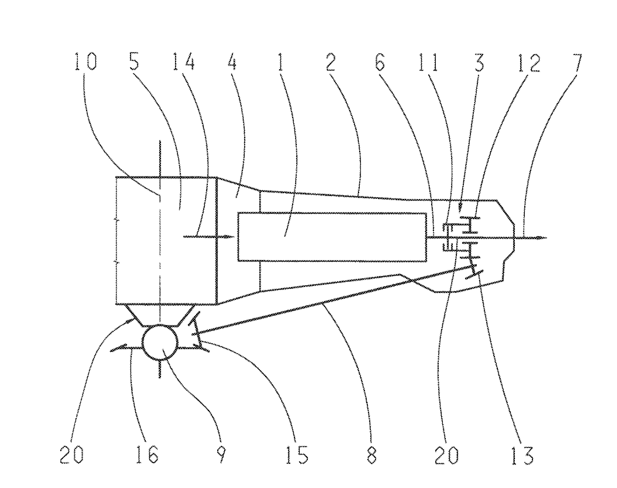
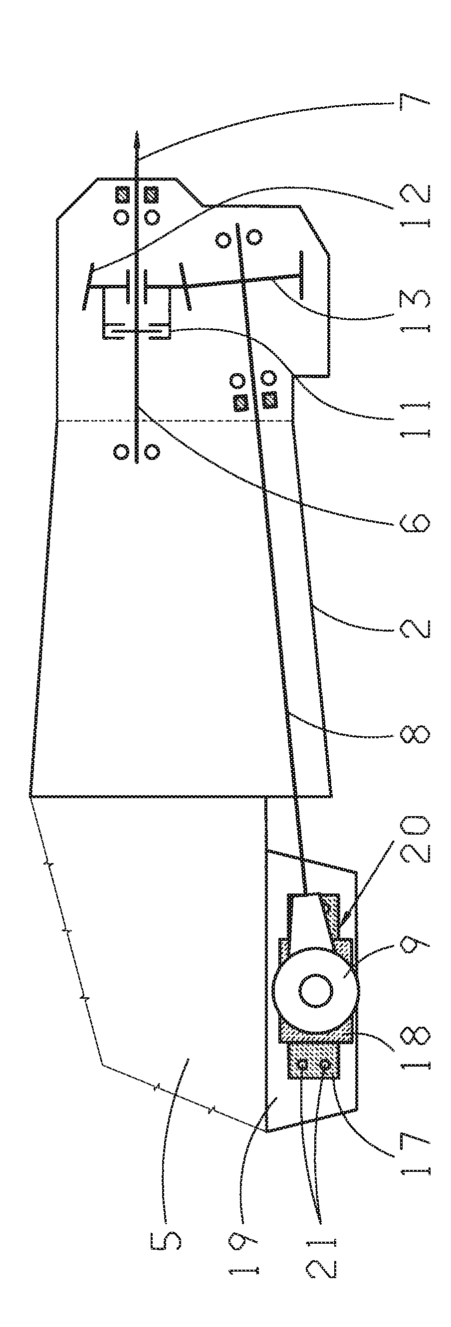
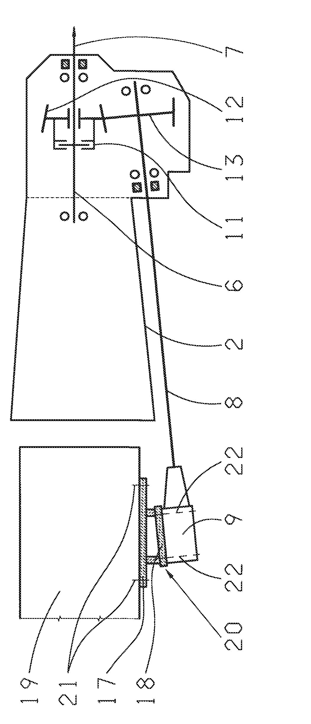
[0023] A possible embodiment of the drive train for a vehicle according to the invention is shown by way of example in the drawing, which has a main transmission 1 in which a transfer case 3 is integrated in a transmission housing 2 . In the drive train according to the invention, for example, an adjustable all-wheel drive can be provided, but also a purely rear-axle drive or a front-axle drive.

[0024] exist figure 1 shows an example of an adjustable all-wheel drive in a vehicle as a drive train. The drive train comprises the main transmission 1 , which is coupled via a starting element 4 with a drive motor 5 for torque transmission. The output shaft 6 of the main transmission 1 is connected to a shaft of the transfer case 3 . The output side of the transfer case 3 is permanently connected to a rear axle differential, indicated only schematically by arrow 7 . Furthermore, the output side of the transfer case 3 can also be selectively coupled via a torque transmission elem...


PUM


Abstract

The invention relates to a drive train arrangement for a vehicle having a main transmission (1), in the transmission housing (2) of which a transfer case (3) is integrated, the output of which is connected to a rear-axle differential gear, wherein the output of the transfer case (3) additionally can be coupled with a front-axle differential gear (9) through a connecting shaft (8) using a torque transmission element, wherein the connecting shaft (8) is arranged at a predefined angle to the output shaft (6) of the main transmission (1), and wherein the end of the connecting shaft (8) facing the front-axle differential gear (9) is operatively connected to the front-axle differential gear (9). According to the invention, the front-axle differential gear (9) is fastened using at least one adapter device (20) on the vehicle side for adjustment to a changed arrangement position along the axis of rotation of the connecting shaft (8).

Description

technical field [0001] The invention relates to a drive train for a vehicle of the type specified in the preamble of claim 1 . Background technique [0002] A transmission for vehicles with four-wheel drive is known from DE 30 36 445 C2. This known automatic transmission is connected downstream of a vehicle engine, wherein the transmission is connected with its first output shaft to the drive shaft for the rear axle and with its second output shaft to the drive shaft for the front axle. The drive power of the front wheel drive takes place via a linkage. [0003] Furthermore, another drive train for a vehicle is known from DE 20 2004 018 036 U1. In this known drive train, the engine is arranged upstream of the rear axle and downstream of the front axle. The driven shaft of the engine extends downstream and is coupled to an automatic transmission via a friction clutch arrangement. The driven end of the automatic transmission is permanently connected via a gear stage to an ...

Claims


Application Information

Patent Timeline
Patent Type & Authority Applications(China)
IPC IPC(8): B60K17/16B60K17/344
CPCB60K17/35
Inventor M·盖尔D·戈林L·拜冈U·迈尔D·巴施T·罗泽迈尔
Owner ZF FRIEDRICHSHAFEN AG
Why Eureka
Try Eureka