Non-contact power transmission device of capacitive coupling type

A non-contact, power transmission technology, applied in the direction of induction generators, etc., can solve the problems of electromagnetic interference in the external environment, limited current carrying capacity, coil heating, etc., to achieve the effect of improving service life, improving coupling degree, and avoiding coil heating

Inactive Publication Date: 2011-08-10
舟山市质量技术监督检测院
View PDF4 Cites 1 Cited by
  • Summary
  • Abstract
  • Description
  • Claims
  • Application Information

AI Technical Summary

Problems solved by technology

This method needs to wind a coupling coil, and the AC resistance of the coil under high-frequency alternating current is much greater than the DC resistance, so the coil generates serious heat, which limits its current-carrying capacity and causes serious losses.
On the other hand, the alternating magnetic field will cause serious electromagnetic interference to the external environment

Method used


Image

  • Non-contact power transmission device of capacitive coupling type
  • Non-contact power transmission device of capacitive coupling type
  • Non-contact power transmission device of capacitive coupling type

Examples


Embodiment Construction

[0015] Further illustrate the present invention below in conjunction with accompanying drawing.

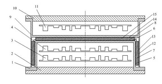
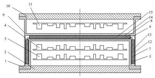
[0016] Refer to attached Figure 1-2 , The capacitively coupled non-contact power transmission device of the present invention includes a power transmitting component and a power picking component installed on a coaxial line.

[0017] The power transmitting assembly includes: a base turntable 1, a base end cover 2, a power conversion circuit board 3, an input control circuit board 4, a first emission capacitor plate 5, a second emission capacitor plate 6, and a first emission capacitor plate Coating 7, the second emission capacitor plate coating 8, the emission capacitor plate coating is made of lead zirconate titanate material; the base turntable 1 and the base end cover 2 form the emission circuit cavity, the power conversion circuit board 3 and the input control circuit board 4 Place it in the cavity of the transmitting circuit, and convert the received external input voltage ...


PUM


Abstract

The invention discloses a non-contact power transmission device of a capacitive coupling type, belonging to the technical field of electromechanical equipment. The non-contact power transmission device of the capacitive coupling type comprises an power transmission assembly and an power pickup assembly which are in coaxial mounting, wherein the power transmission assembly comprises a transmitter circuit chamber formed by a base turntable (1) and a base end cover (2); a power conversion circuit board (3) and an input control circuit board (4) are arranged in the transmitter circuit chamber; a first transmitter capacitor polar board (5) and a second transmitter capacitor polar board (6) are respectively attached to the lateral surface and the end surface of the base turntable (1), the surfaces of the polar boards are coated with lead zirconate titanate (8 and 9); the power pickup assembly comprises a pickup circuit chamber formed by an end cover turntable (9) and an end cover end cover (10), and a rectifier circuit board (11) is arranged in the pickup circuit chamber; a first pickup capacitor polar board (12) and a second pickup capacitor polar board (13) are respectively attached to the inner side surface and the bottom surface of a hollow chamber at the front end of the end cover turntable (9); and the surfaces of the polar boards are coated with lead zirconate titanate (12 and 13). By means of the non-contact power transmission device, non-contact power transmission is realized in a capacitive coupling mode, and the problems, such as electromagnetic interference, coil heating, and the like are avoided.

Description

technical field [0001] The invention relates to a capacitive coupling type non-contact power transmission device, which belongs to the technical field of electromechanical equipment. technical background [0002] In the type inspection of ship products, test items such as flushing, water spraying, and water pressure will be involved. Therefore, the test environment is often in a humid and watery state, and the power transmission interface of the electromechanical equipment working in this environment must be strictly waterproof. Only when it is sealed can it be used, otherwise leakage, short circuit and other phenomena will occur, causing damage to the equipment and even injury to the operator. The non-contact power transmission method can avoid direct contact between the power transmission interface circuit and the humid environment, and improve the safety and reliability of the equipment. However, the electromagnetic induction non-contact power transmission method commonl...

Claims


Application Information

Patent Timeline
Patent Type & Authority Applications(China)
IPC IPC(8): H02N1/08
Inventor 李泽松
Owner 舟山市质量技术监督检测院
Why Eureka
Try Eureka