Vacuum heat insulation panel air pressure sealing machine and sealing process for sealing vacuum heat insulation panel utilizing same
A vacuum insulation panel and sealing machine technology, which is applied in mechanical equipment, heat exchange equipment, and pipelines through thermal insulation protection, etc., can solve the problems of wrinkling and deformation of aluminum foil barrier bags, the contact surface of sealing is not compact, and the quality of products is affected. The effect of improving product quality, reasonable structure, improving thermal insulation performance and service life
- Summary
- Abstract
- Description
- Claims
- Application Information
AI Technical Summary
Problems solved by technology
Method used
Image
Examples
Embodiment 1
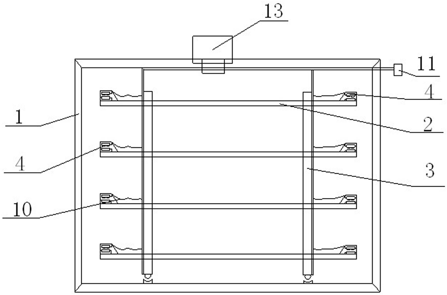
[0016] Such as figure 1 As shown in -3, the air pressure sealing machine for vacuum insulation panels of the present invention includes a box body 1, a vacuum pump 13 arranged above the box body 1, a plurality of racks 2 arranged in the box body 1, and a machine for supporting the racks 2 Frame 3, each end of rack 2 is provided with sealing device 4, and each sealing device 4 comprises upper and lower layers of bakelite 5 and 6 fixed on rack 2, and silica gel strip 8 attached to lower layer of bakelite 6 , an arc-shaped support frame 12 is provided below the upper bakelite 5, and two heating sealing strips 7 are arranged on the arc-shaped support frame 12. The part of the silicone strip 8 protrudes above the lower layer of bakelite 6, and the rest of the silicone strip 8 is embedded in the lower layer. In the bakelite 6, the upper bakelite 5 is provided with an air bag 9, and the air bag 9 is connected with an external air source 11 through a trachea 10.
[0017] The sealing ...
Embodiment 2
[0019] Such as figure 1 As shown in -3, the air pressure sealing machine for vacuum insulation panels of the present invention includes a box body 1, a vacuum pump 13 arranged above the box body 1, a plurality of racks 2 arranged in the box body 1, and a machine for supporting the racks 2 Frame 3, each end of rack 2 is provided with sealing device 4, and each sealing device 4 comprises upper and lower layers of bakelite 5 and 6 fixed on rack 2, and silica gel strip 8 attached to lower layer of bakelite 6 , an arc-shaped support frame 12 is provided below the upper bakelite 5, and two heating sealing strips 7 are arranged on the arc-shaped support frame 12. The part of the silicone strip 8 protrudes above the lower layer of bakelite 6, and the rest of the silicone strip 8 is embedded in the lower layer. In the bakelite 6, the upper bakelite 5 is provided with an air bag 9, and the air bag 9 is connected with an external air source 11 through a trachea 10.
[0020] The sealing ...
Embodiment 3
[0022] Such as figure 1 As shown in -3, the air pressure sealing machine for vacuum insulation panels of the present invention includes a box body 1, a vacuum pump 13 arranged above the box body 1, a plurality of racks 2 arranged in the box body 1, and a machine for supporting the racks 2 Frame 3, each end of rack 2 is provided with sealing device 4, and each sealing device 4 comprises upper and lower layers of bakelite 5 and 6 fixed on rack 2, and silica gel strip 8 attached to lower layer of bakelite 6 , an arc-shaped support frame 12 is provided below the upper bakelite 5, and two heating sealing strips 7 are arranged on the arc-shaped support frame 12. The part of the silicone strip 8 protrudes above the lower layer of bakelite 6, and the rest of the silicone strip 8 is embedded in the lower layer. In the bakelite 6, the upper bakelite 5 is provided with an air bag 9, and the air bag 9 is connected with an external air source 11 through a trachea 10.
[0023] The sealing ...
PUM
 Abstract
Description
Claims
Application Information
 - Generate Ideas
- Intellectual Property
- Life Sciences
- Materials
- Tech Scout
- Unparalleled Data Quality
- Higher Quality Content
- 60% Fewer Hallucinations
Browse by: Latest US Patents, China's latest patents, Technical Efficacy Thesaurus, Application Domain, Technology Topic, Popular Technical Reports.
© 2025 PatSnap. All rights reserved.Legal|Privacy policy|Modern Slavery Act Transparency Statement|Sitemap|About US| Contact US: help@patsnap.com


