
Pumping system and distributing valve thereof, and concrete transporting machinery

A pumping system and distribution valve technology, which is applied in the field of concrete mixing pump trucks and concrete conveying machinery, can solve problems such as adaptability, service life is difficult to meet actual needs, the application of concrete mixing pump trucks is difficult, and the requirements for driving mechanisms are high.

Active Publication Date: 2011-08-10
SANY AUTOMOBILE MFG CO LTD
View PDF8 Cites 22 Cited by
  • Summary
  • Abstract
  • Description
  • Claims
  • Application Information

AI Technical Summary

Problems solved by technology

[0006] The prior art also discloses a distributing valve that does not need to be used in conjunction with an open hopper, such as a multi-position and multi-way "S" pipe valve disclosed in Chinese patent document CN1336487A. High, it is very difficult to apply in concrete mixing pump trucks; German patent document DE4204330B4 discloses a distribution valve that realizes material distribution through a rotor hose pump, but the working performance of this distribution valve is highly dependent on the hose, so that Its adaptability and service life are difficult to meet actual needs

Method used


Image

  • Pumping system and distributing valve thereof, and concrete transporting machinery
  • Pumping system and distributing valve thereof, and concrete transporting machinery
  • Pumping system and distributing valve thereof, and concrete transporting machinery

Examples


Embodiment Construction

[0039] The present invention will be described in detail below in conjunction with the accompanying drawings. The description in this part is only exemplary and explanatory, and should not have any limiting effect on the protection scope of the present invention.

[0040] It should be noted that the technical solution provided by the present invention is not limited to pumping or conveying concrete, and can also be used to convey ash, mud or other viscous materials.

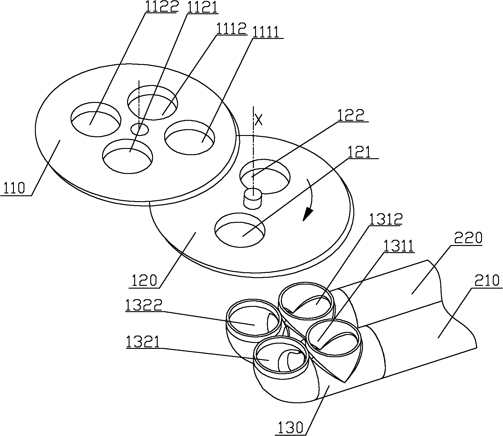
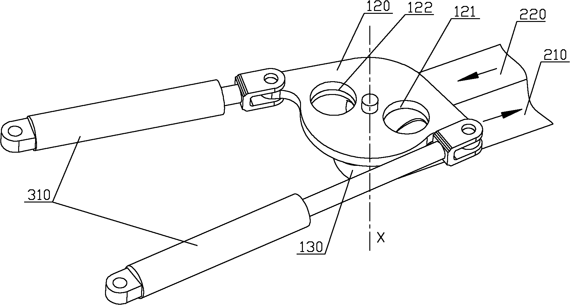
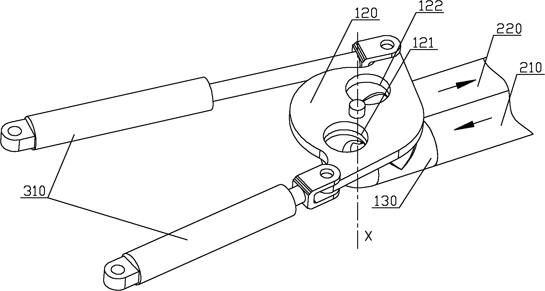
[0041] Please refer to figure 1 and figure 2 , figure 1 It is a schematic diagram of the exploded structure of the distributing valve of the pumping system provided by the embodiment of the present invention, figure 2 is a schematic structural view of the distribution valve of the pumping system provided by the embodiment of the present invention when it is in the first state, image 3 It is a schematic structural diagram of the distribution valve of the pumping system provided by the embodiment of the prese...


PUM


Abstract

The invention discloses a pumping system and a distributing valve thereof, and concrete transporting machinery. The distributing valve of the pumping system comprises a first valve body plate, a second valve body and a rotatable valve plate, wherein the first valve body plate and the second valve body are respectively in sliding matching with two surfaces of the valve plate; the distributing valve has two states, in the first state, a first sucking hole is communicated with a material container through a first passing communicating hole, and a second discharging hole is communicated with a second pumping hole through a second passing communicating hole; and in the second state, a second sucking hole is communicated with the material container through a passing communicating hole, and a first discharging hole is communicated with a first pumping hole through the other passing communicating hole or the first passing communicating hole. The valve plate of the distributing valve does not need to rotate in a hopper, and the distributing valve does not need to be matched with an opening hopper for use; meanwhile, the state conversion of the distributing valve is realized through the rotary valve plate, a driving force required by the distributing valve during state conversion is greatly reduced, and the energy consumption of the distributing valve can be reduced.

Description

technical field [0001] The invention relates to a pumping technology for viscous materials such as concrete, in particular to a distribution valve of a pumping system, and also to a pumping system including the distribution valve and a concrete conveying machine including the pumping system , the concrete conveying machinery particularly refers to a concrete mixing pump truck. Background technique [0002] Concrete mixer truck is the most widely used concrete conveying machinery and equipment. Concrete mixing pump trucks generally include a chassis, a mixing mechanism, a pumping system and a distribution mechanism. The mixing mechanism generally includes a mixing drum; the pumping system includes a hopper, a distribution valve and a delivery cylinder; the distribution mechanism usually includes an arm frame formed by at least two arms, and a delivery pipe is arranged along the arm frame. The basic working principle of the concrete mixer pump truck is: the mixing drum rotat...

Claims


Application Information

Patent Timeline
IPC IPC(8): F04B53/10F04B15/02E04G21/04B28C5/00
Inventor 易秀明郭承志夏益民
Owner SANY AUTOMOBILE MFG CO LTD
Learn More